Back flow prevention valve

A technology of check valves and check valves, which is applied to control valves, valve devices, valve details, etc., can solve problems such as damage to cleaning devices, and achieve the effect of small structural volume and simplified spare parts storage

Inactive Publication Date: 2009-04-15
ALFRED KARCHER GMBH & CO KG
View PDF4 Cites 0 Cited by
  • Summary
  • Abstract
  • Description
  • Claims
  • Application Information

AI Technical Summary

Problems solved by technology

However, at this point the pressure buildup in the region of the discharge opening could lead to damage to the non-return valve or the cleaning device connected to it

Method used


Image

  • Back flow prevention valve
  • Back flow prevention valve
  • Back flow prevention valve

Examples


Embodiment Construction

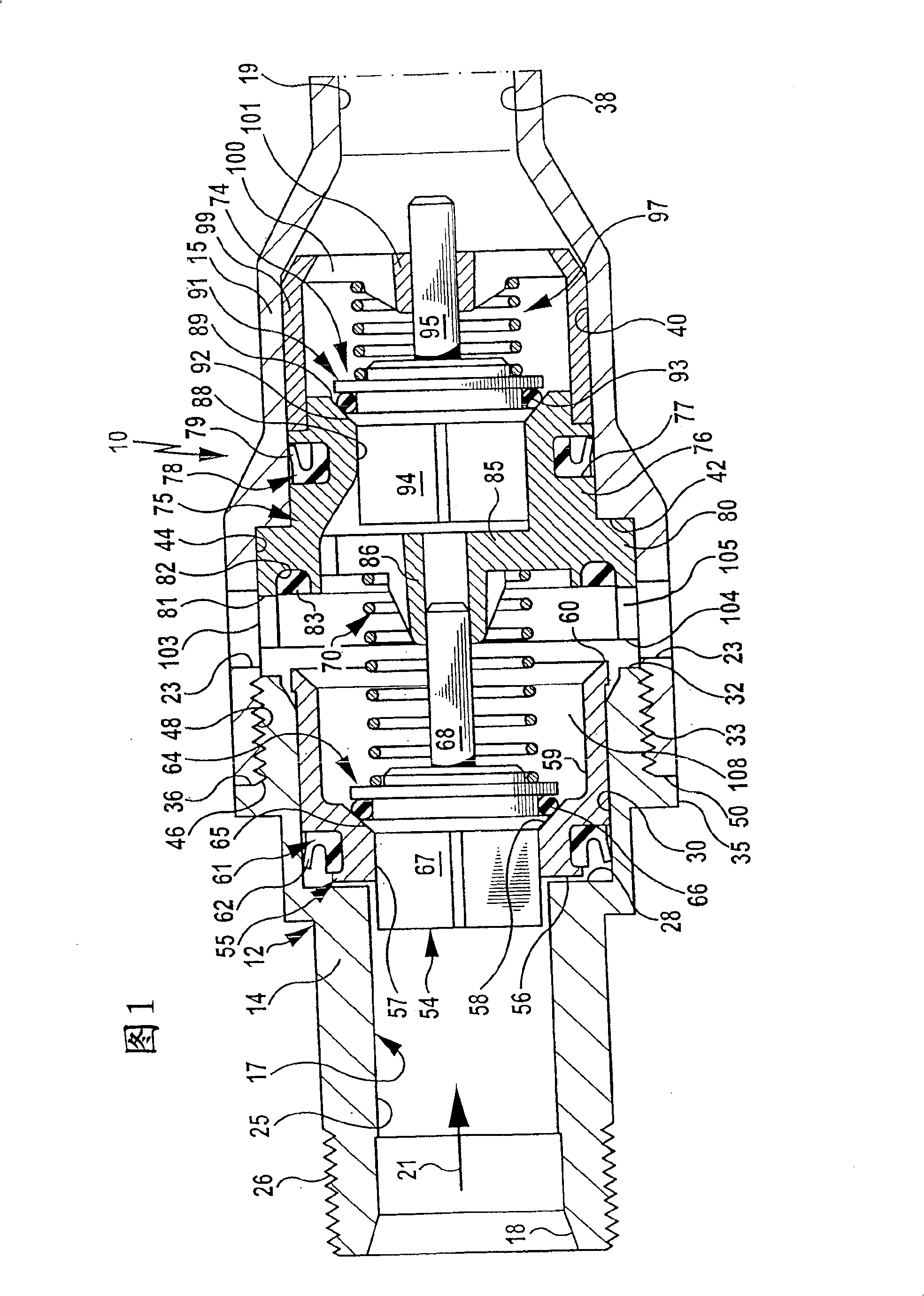
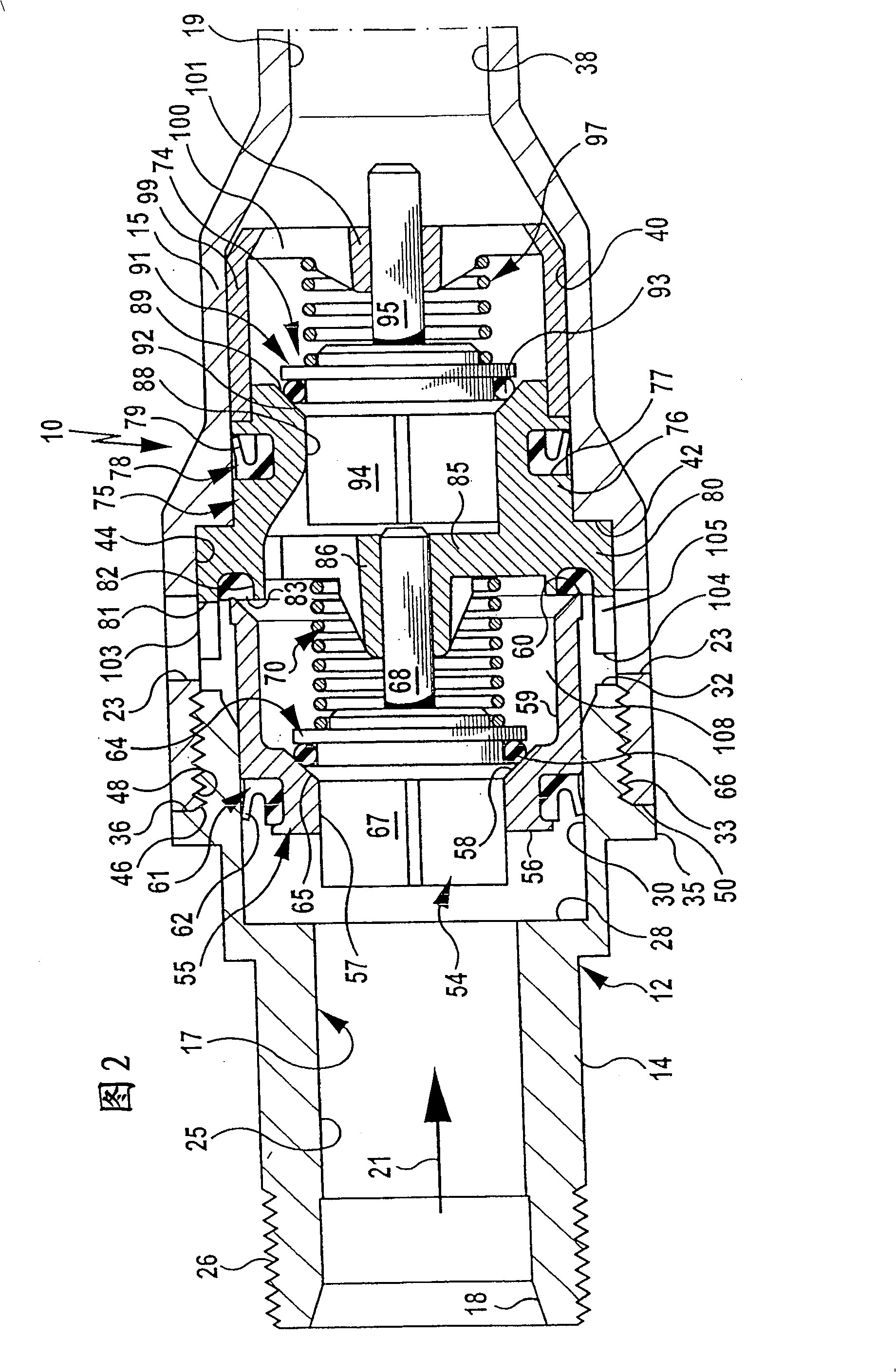
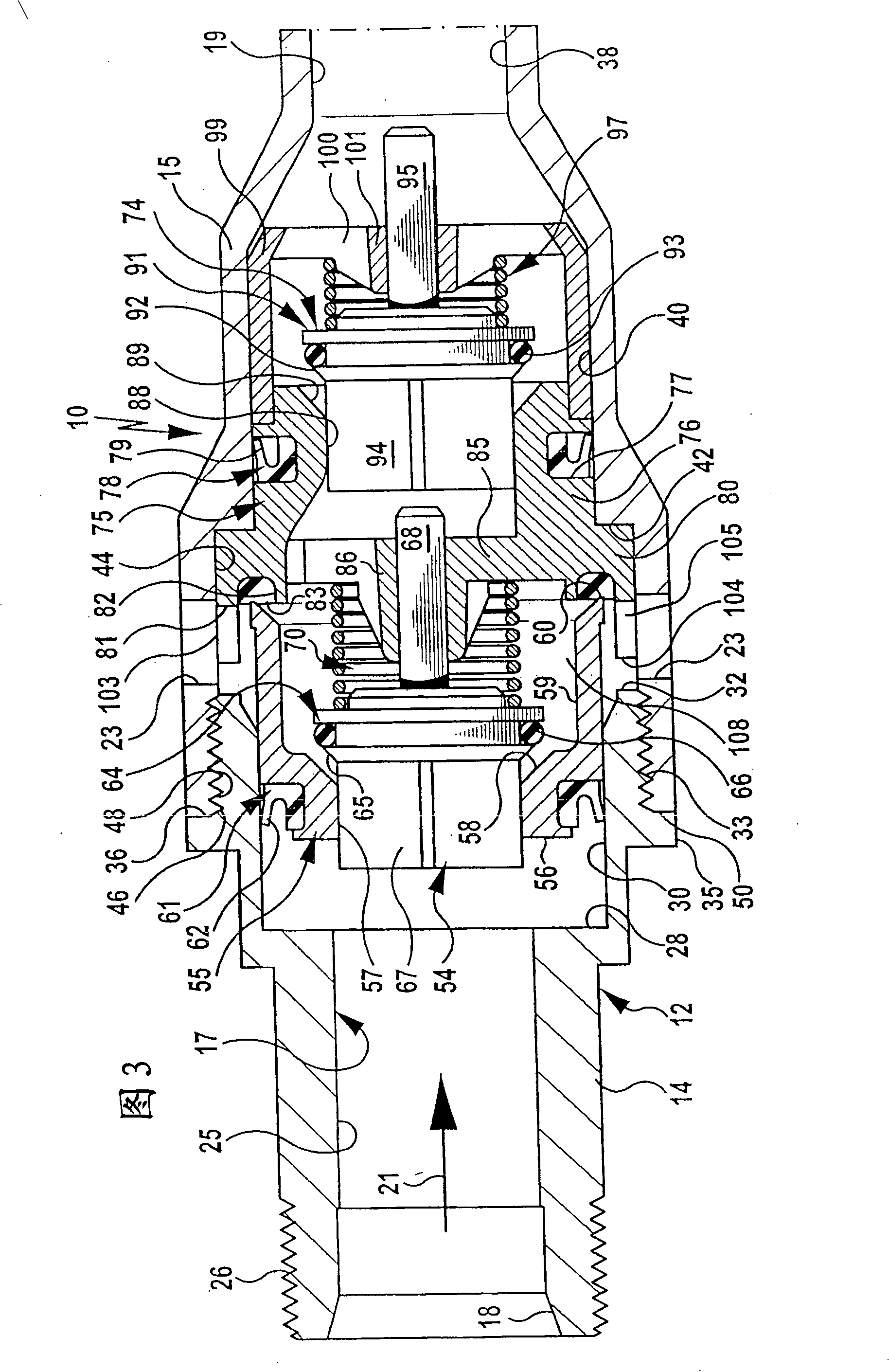
[0025] There is shown a check valve, generally indicated at 10, comprising a two-part housing 12 having a first housing part 14 and a second housing part 15 and enclosing a flow passage 17 communicating with An inlet 18 and an outlet 19 , wherein at least one, preferably a plurality of leakage openings distributed along the circumference of the housing 12 are formed in the housing 12 approximately centrally in the flow direction 21 between the inlet 18 and the outlet 19 twenty three.

[0026] The first housing part 14 constitutes the form of a pipe part and includes an inlet passage 25 connected on the inlet 18, which has an external thread 26 on the outside for connecting the non-return valve 10 on a drinking water supply pipe and via A step 28 merges into a connecting portion 30 whose inner diameter is greater than that of the inlet channel 25 and which terminates with an end face 32 whose plane normal is situated parallel to the flow direction 21 . The part of the connecti...


PUM


Abstract

The invention relates to a backflow preventer comprising a housing that is provided with an inlet port, an outlet port, and a leakage opening which is located between said ports. The housing accommodates a first and a second check valve which are arranged one behind the other. The first check valve is retained in a movable manner within the housing and opens or blocks a flow connection between an interior space of the housing and the leakage opening by moving said check valve. In order to further develop said backflow preventer in such a way that the pressure can be prevented, in a simple structural fashion, from unduly increasing in the area of the outlet port, the second check valve is retained in a movable manner within the housing while the first check valve continues to be movable.

Description

technical field [0001] The invention relates to a non-return valve, especially for connecting a high-pressure cleaning device to a drinking water supply pipeline, comprising a housing with an inlet, an outlet and a valve arranged in the flow direction at the inlet. The leakage port between the discharge port and accommodates a first and a second non-return valve, which are arranged consecutively in the flow direction, wherein the first non-return valve is movably supported in the housing and passes through the first non-return valve Movement of the valve opens or isolates fluid communication between a housing lumen disposed between the two check valves and the leak port. Background technique [0002] Such non-return valves are also known as "line flow breakers" and are known from laid-open document DE 24 24 978 A1. If cleaning devices, such as high-pressure cleaners or washing machines, are to be connected to a drinking water supply, it must be ensured that contaminated cle...

Claims


Application Information

Patent Timeline
Patent Type & Authority Patents(China)
IPC IPC(8): E03C1/10F16K15/06F16K47/02
CPCE03C1/106E03C1/10F16K15/066E03C1/108
Inventor R·克劳特M·克勒普弗
Owner ALFRED KARCHER GMBH & CO KG
Why Eureka
Try Eureka