Co-layer drainage system

A technology of same-layer drainage and drainage branch pipes, which is applied in flushing toilets, water supply devices, indoor sanitary pipeline installations, etc., can solve problems such as affecting the appearance, dripping, disputes, etc., and achieve the effect of improving aesthetics and facilitating cleaning and dredging

Inactive Publication Date: 2009-05-06
陆正新
View PDF7 Cites 0 Cited by
  • Summary
  • Abstract
  • Description
  • Claims
  • Application Information

AI Technical Summary

Problems solved by technology

[0002] Existing buildings, especially in the bathrooms of residential buildings, are equipped with sewage discharge devices. The current sewage discharge devices cannot meet the national standards for laying drainage branch pipes in this floor. When installing, holes must be drilled on the floor. Install the sewage discharge pipes on this floor on the top of the bathroom on the next floor. The exposed hanging pipes are not only prone to aging and dripping, but also affect the rest of the residents on the lower floor due to the noise generated by the residents on the upper floor during the drainage process.
And once the drip phenomenon occurs, it is necessary to go to the houses of the lower-level users to clear and repair it, which will easily cause conflicts between the upper and lower-level residents and cause neighborhood disputes.
Since the drainage pipelines of the upper residents must be installed on the top of the bathrooms of the lower residents, the rough pipelines greatly affect the appearance. For this reason, ordinary users will hang the ceiling in the bathroom to cover the exposed pipelines on the top
The layout of sanitary ware must be aligned with the upper and lower floors to facilitate the layout of pipelines, which restricts residents from arranging the bathroom facilities in the bathroom according to their own preferences

Method used


Image

  • Co-layer drainage system
  • Co-layer drainage system
  • Co-layer drainage system

Examples


Embodiment Construction

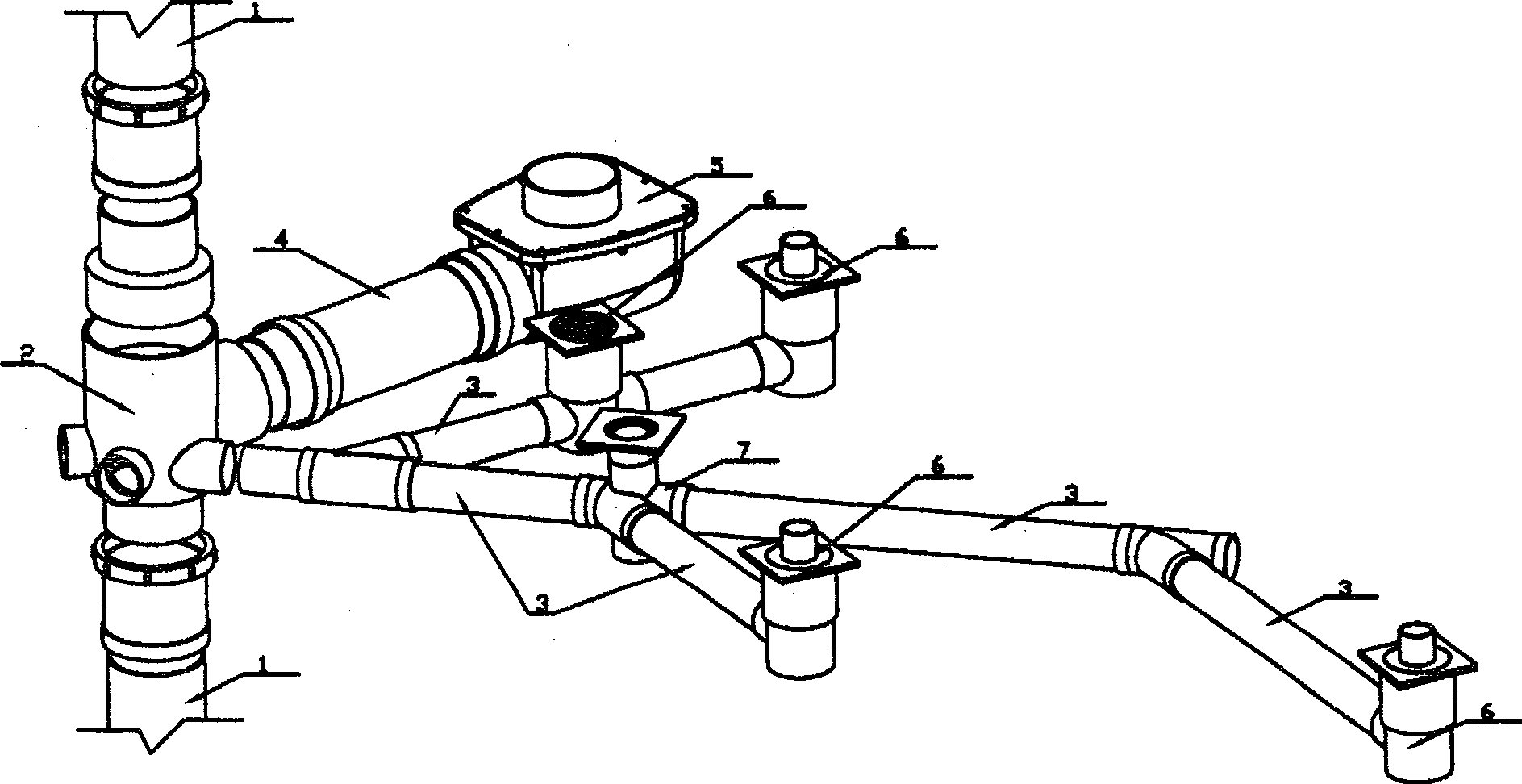
[0022] Such as figure 1 As shown, a drainage system on the same floor according to the present invention includes a main pipe 1 running through each floor, a multi-channel joint 2, a sewage branch pipe 3, a drainage branch pipe 4, a toilet connector 5, a multi-functional floor drain 6 and multiple The function is the water-flow tee 7, the multi-channel joint 2 is installed on the main pipe 1 passing through the floor, the branch pipes 3 and 4 laid in the floor are connected with the multi-channel joint 2, and the toilet connector 5 is installed on the sewage branch pipe 3, Install multi-functional floor drain 6 and multi-functional downstream tee 7 on drainage branch pipe 4. The branch pipe 3 has a certain installation inclination toward the water outlet when it is laid, and the toilet seat connector 5, the multifunctional floor drain 6 and the water-flowing tee 7 are all connected to the multi-channel joint 2 through the branch pipe.

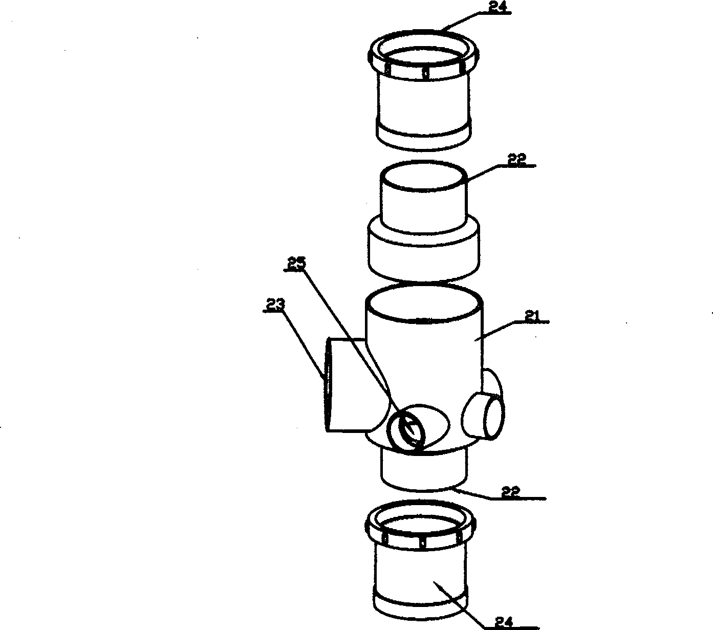
[0023] Such as figure 2 As shown, the...


PUM


Abstract

The present invention discloses a same-floor drainage system. Said same floor drainage system includes the following several portions: main pipe passed through all the floors, multi-channel adaptors, branch pipes, toilet connectors, multifunctional floor drains and three-way valves. Said invention also provides the concrete connection mode of all the above-mentioned portions and the concrete working principle of said same floor drainage system.

Description

1. Technical field [0001] The invention relates to a drainage system, in particular to a same-floor drainage system laid in floor floors. 2. Background technology [0002] Existing buildings, especially in the bathrooms of residential buildings, are equipped with sewage discharge devices. The current sewage discharge devices cannot meet the national standards for laying drainage branch pipes in this floor. When installing, holes must be drilled on the floor. The sewage discharge pipes on this floor are installed on the top of the bathroom on the next floor. The exposed hanging pipes are not only prone to aging and dripping, but also affect the rest of the residents on the lower floor due to the noise generated by the residents on the upper floor during the drainage process. And in case drip phenomenon takes place, will go clearing and repairing in the dwelling of lower-level user, easily make upper and lower-level resident produce conflict and cause neighborhood dispute like...

Claims


Application Information

Patent Timeline
Patent Type & Authority Patents(China)
IPC IPC(8): E03C1/12E03C1/28E03D11/17
Inventor 陆正新
Owner 陆正新
Why Eureka
Try Eureka