Method for driving element extending along longitudinal axis

A technology in the direction of the longitudinal axis and the longitudinal axis, which is applied in the direction of pipes/pipe joints/fittings, pipe supports, mechanical equipment, etc., and can solve problems such as unrealizable and impossible to achieve

Inactive Publication Date: 2009-05-06
SIEMENS AG
View PDF4 Cites 0 Cited by
  • Summary
  • Abstract
  • Description
  • Claims
  • Application Information

AI Technical Summary

Problems solved by technology

Due to sometimes exceptionally long cable dimensions, this is almost impossible or not possible at all

Method used


Image

  • Method for driving element extending along longitudinal axis
  • Method for driving element extending along longitudinal axis
  • Method for driving element extending along longitudinal axis

Examples


Embodiment Construction

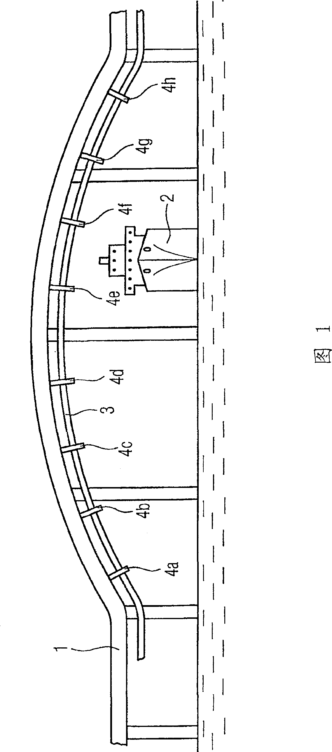
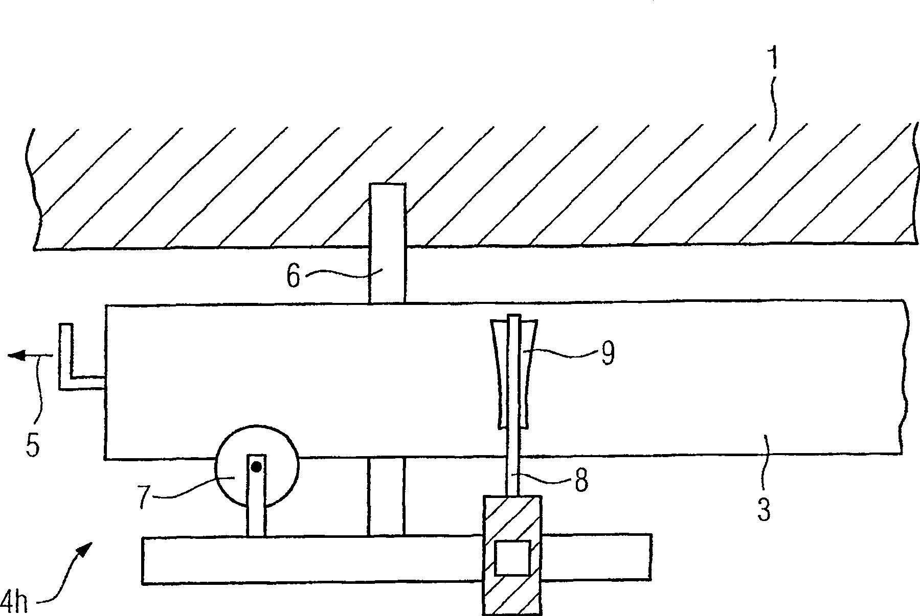
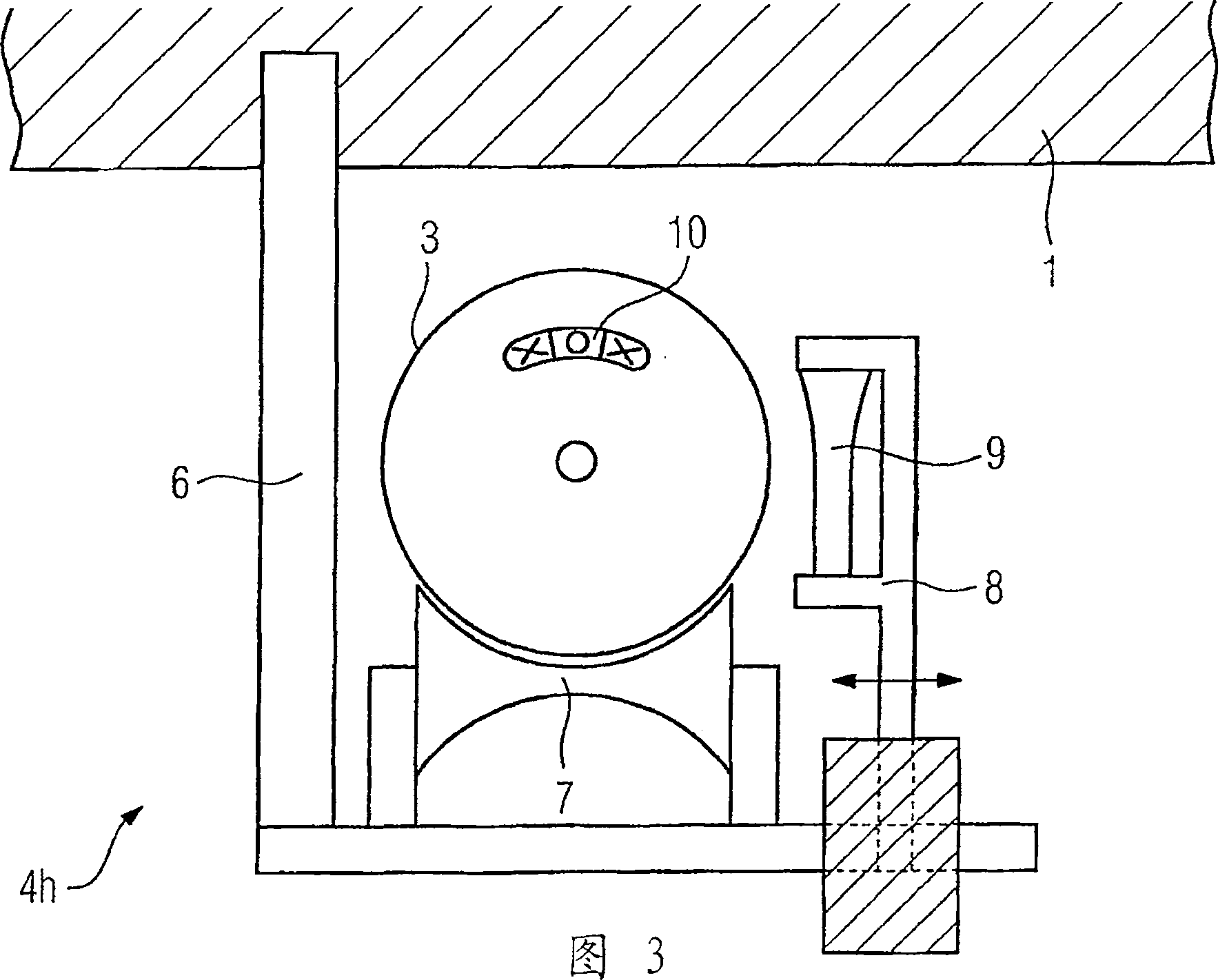
[0026] Figure 1 shows a bridge 1 spanning a water surface area. The bridge 1 has curved arches to enable tall ships 2 to pass. The gas insulated electrical conductor 3 needs to be laid on the bridge 1 according to the arc of the bridge. For this purpose, a plurality of roller bearing arrangements 4 a , 4 b , 4 c , 4 d , 4 e , 4 f , 4 g , 4 h are provided on the bridge 1 . Due to bending, the gas-insulated electrical conductor 3 can generate mechanical stresses that cause it to rotate about the longitudinal axis. The gas-insulated electrical conductor 3 can be designed essentially to consist of, for example, a metallic outer sleeve, inside which the actual electrical conductor is arranged. The electrical conductor is supported on the tubular outer housing by means of an electrically insulating support element. The interior of the gas-insulated electrical conductor 3 is filled with an insulating gas under operating conditions. The gas-insulated electrical conductor 3 with a ...


PUM


Abstract

A number of roller bearing arrangements (4a, b, c, d, e, f, g, h) are provided for laying a gas-insulated electrical conductor (3). The roller bearing arrangements (4a, b, c, d, e, f, g, h) comprise rotationally mounted rollers (7) on which the gas-insulated electrical conductors (3) rests and is moved. A braking device (8), which acts upon the gas-insulated electrical conductor (3), prevents the gas-insulated electrical conductor (3) from rotating about its longitudinal axis when being laid.

Description

technical field [0001] The invention relates to a method for advancing an element extending along a longitudinal axis, wherein the element is placed on at least one rotatably mounted roller of at least one roller bearing and is displaceable along the longitudinal axis. Background technique [0002] Roller bearing arrangements for laying power transmission cables are well known. When the cable is drawn into the cable trench or on the cable rack, the cable rests on rotatably mounted rollers of one or more roller bearings. This makes it easy to move several meters of cable end and protects the cable sheath from damage or mechanical wear. [0003] Depending on the conditions at the site where the cables are laid, it is sometimes necessary to guide the cables as movable elements by means of bends or around corners. The resulting mechanical stress causes the cable to twist. However, a certain positional state of the displaced element should often be ensured in order, for exampl...

Claims


Application Information

Patent Timeline
IPC IPC(8): F16L3/18
CPCF16L3/18
Inventor 赫尔曼·科克
Owner SIEMENS AG
Why Eureka
Try Eureka