Level adjustment systems and adjustable pin chuck thereof

A technology for adjusting system and flatness, which is applied in the field of flatness adjustment system for flatness, which can solve the problem of photoresist leaving and achieve the effect of good flatness

Active Publication Date: 2009-05-20
TAIWAN SEMICON MFG CO LTD
View PDF8 Cites 4 Cited by
  • Summary
  • Abstract
  • Description
  • Claims
  • Application Information

AI Technical Summary

Problems solved by technology

However, since the distance D between the lens 33 of the stepper or scanning exposure device 3 and the photoresist 4 of the wafer W is usually very small (for example, between 1 mm and 10 mm), the uneven wafer W The change in distance D caused by the surface will cause its photoresist to leave the focus range of the lens 33

Method used


Image

  • Level adjustment systems and adjustable pin chuck thereof
  • Level adjustment systems and adjustable pin chuck thereof
  • Level adjustment systems and adjustable pin chuck thereof

Examples


no. 1 example

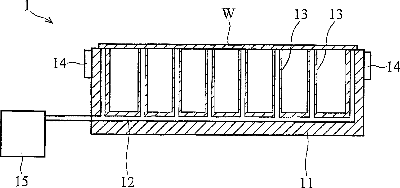
[0086] see Figure 4 , the flatness adjustment system 100 of this embodiment mainly includes an adjustable needle-type bearing suction cup 110 , an air suction device 120 , a flatness detection device 130 and a length control device 140 .

[0087] Another example Figure 4 As shown, the adjustable needle-type bearing suction cup 110 has a base 111 and a plurality of adjustable thimbles 112 . At the same time, the base 111 also has a concave portion 113 and an air extraction pipeline 114 , the air extraction pipeline 114 is connected to the concave portion 113 , and a plurality of adjustable thimbles 112 are evenly arranged in the concave portion 113 . In this embodiment, each adjustable thimble 112 also has a piezoelectric element 115 and a bearing element 116 , the piezoelectric element 115 is disposed on the base 111 , and the bearing element 116 is disposed on the piezoelectric element 115 . In addition, each bearing element 116 also has an L-shaped through hole 117 , and...

no. 2 example

[0095] In this embodiment, the same elements as those in the first embodiment are marked with the same symbols.

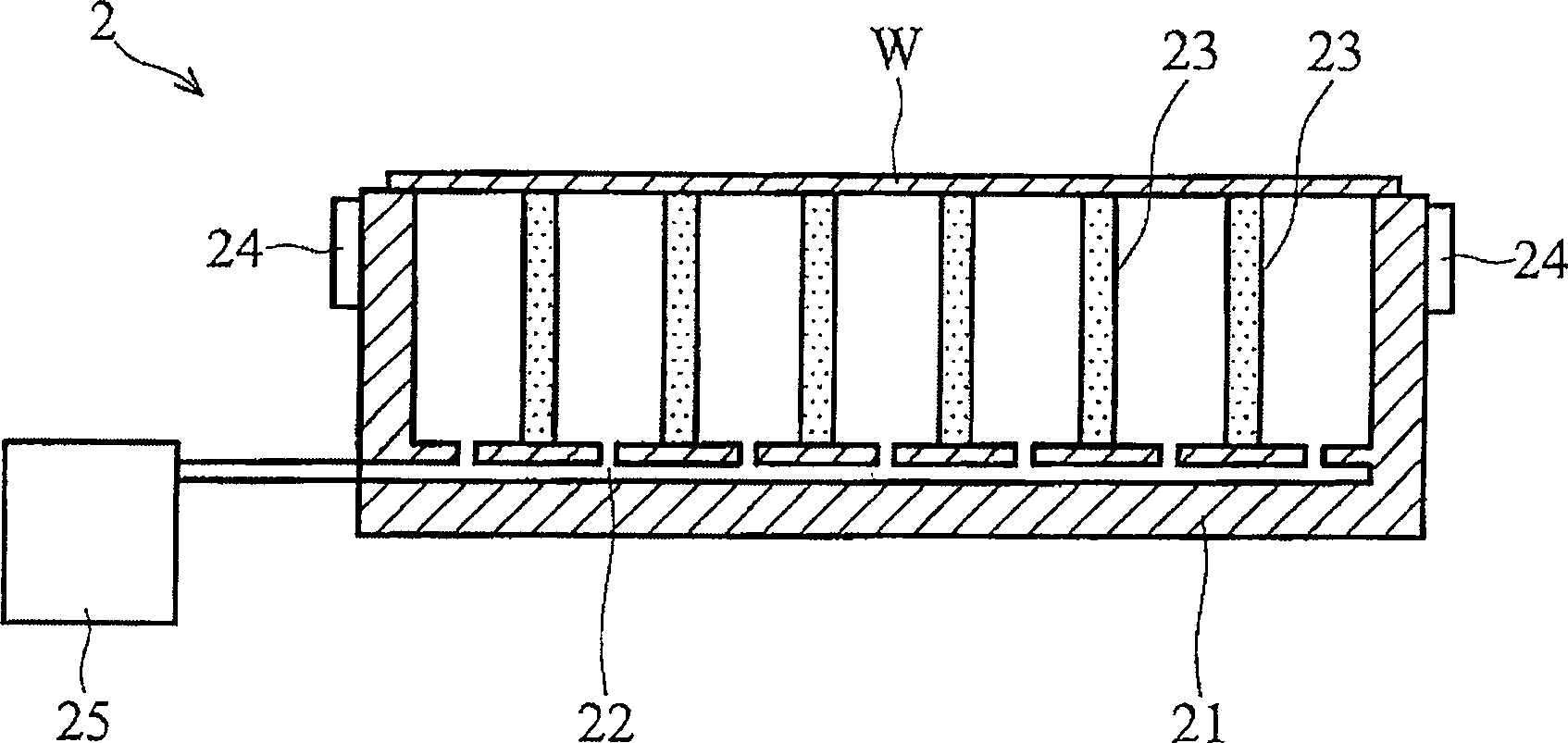
[0096] see Figure 5 , the flatness adjustment system 200 of this embodiment mainly includes an adjustable needle-type bearing suction cup 110 , an air suction device 120 , a flatness detection device 230 and a length control device 140 .

[0097] still as Figure 5 As shown, the flatness detection device 230 is disposed on the adjustable needle-type loading suction cup 110 . More specifically, the flatness detection device 230 of this embodiment is an air pressure rangefinder, and has a plurality of air blowing lines 231 and a plurality of pressure sensors 232 . Each pressure sensor 232 is disposed on each blowing pipeline 231 and is electrically connected to the length control device 140 .

[0098] As for other components or features of this embodiment are the same as those of the first embodiment, in order to make the description of the present invention clea...

no. 3 example

[0102] In this embodiment, the same elements as those in the first embodiment are marked with the same symbols.

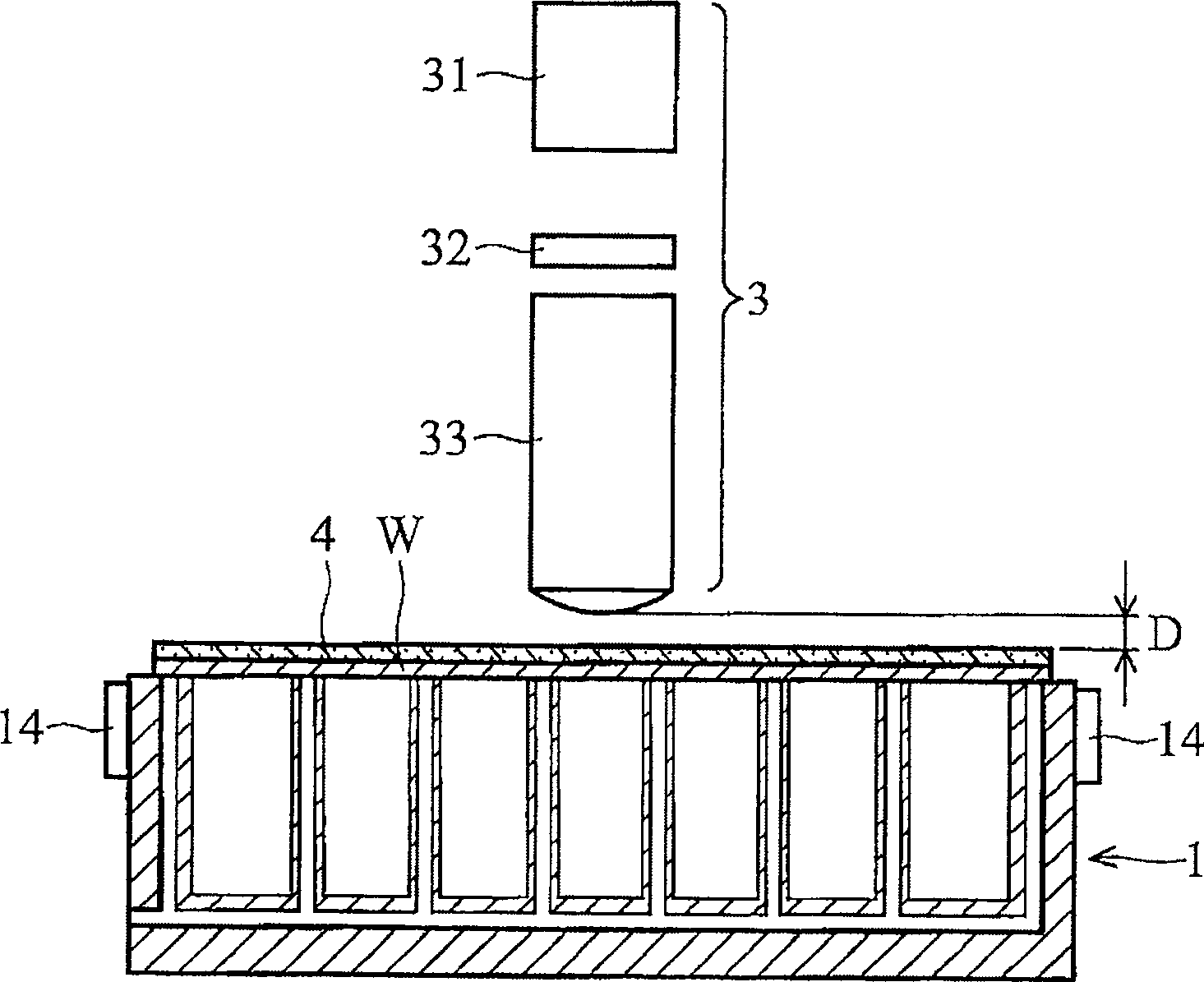
[0103] see Image 6 , the flatness adjustment system 300 of this embodiment mainly includes an adjustable needle-type bearing suction cup 110 , an air suction device 120 , a flatness detection device 330 and a length control device 140 .

[0104] still as Image 6 As shown, the flatness detection device 330 is disposed on the adjustable needle-type loading suction cup 110 . More specifically, the flatness detection device 330 of this embodiment is a capacitive distance meter, and the capacitive distance meter has a plurality of parallel metal sheets 331 , and the plurality of metal sheets 331 are electrically connected to the length control device 140 .

[0105] As for other components or features of this embodiment are the same as those of the first embodiment, in order to make the description of the present invention clearer and easier to understand, repeated d...


PUM


Abstract

A level adjustment system and an adjustable pin chuck are provided by the invention. The level adjustment system includes an adjustable pin chuck, an evacuation device, a level detection device and a length control device. The adjustable pin chuck includes a base and a variable pin to support a substrate. The base includes a recess and an evacuation channel connected thereto. The variable pin is disposed in the recess. The evacuation device is connected to the evacuation channel to evacuate the recess, such that the substrate is attached to the base and variable pin. The level detection device is disposed on the adjustable pin chuck to detect the horizontality of a target surface of the substrate. The length control device is electrically connected to the level detection device and variable pin. The length control device changes the length of the variable pin to adjust level of the target surface of the substrate according to the detected horizontality.

Description

technical field [0001] The invention relates to a flatness adjustment system, in particular to a flatness adjustment system capable of adjusting the flatness of a substrate. Background technique [0002] In the current semiconductor manufacturing process, pin chucks have been widely used to carry wafers so as to perform processes such as exposure on the wafers. [0003] see figure 1 A known needle-type bearing suction cup 1 mainly includes a base 11 , a vacuum pipeline 12 , a plurality of hollow needle-type bearing elements 13 and two interferometer mirrors 14 . A plurality of hollow needle bearing elements 13 are evenly formed on the base 11 , and the vacuum pipeline 12 is located in the base 11 , and the vacuum pipeline 12 is connected to the hollow interior of each hollow needle bearing element 13 . Two interfering mirrors 14 are disposed on two sides of the base 11 and can be used to position the wafer W. [0004] like figure 1 As shown, after the wafer W is placed o...

Claims


Application Information

Patent Timeline
Patent Type & Authority Patents(China)
IPC IPC(8): H01L21/683G03F7/20
CPCH01L21/67259H01L21/67288H01L21/6838H01L21/68742
Inventor 林本坚高蔡胜陈政宏
Owner TAIWAN SEMICON MFG CO LTD
Why Eureka
Try Eureka