
Displacement sensor circuit mounting structure, zoom lens, and imaging device

A technology of displacement sensor and installation structure, which is applied in the direction of focusing device, focusing device, camera focusing device, etc., and can solve the problem that the flatness of the displacement sensor probe cannot be guaranteed, etc.

Pending Publication Date: 2021-07-16
UNION OPTECH
View PDF0 Cites 0 Cited by
  • Summary
  • Abstract
  • Description
  • Claims
  • Application Information

AI Technical Summary

Problems solved by technology

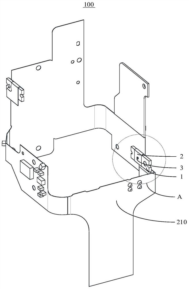
[0003] The main purpose of the present invention is to propose a displacement sensor circuit installation structure, zoom lens and camera device, aiming to solve the problem that the flatness of the displacement sensor probe cannot be guaranteed

Method used


Image

  • Displacement sensor circuit mounting structure, zoom lens, and imaging device
  • Displacement sensor circuit mounting structure, zoom lens, and imaging device
  • Displacement sensor circuit mounting structure, zoom lens, and imaging device

Examples


Embodiment Construction

[0036] The following will clearly and completely describe the technical solutions in the embodiments of the present invention with reference to the accompanying drawings in the embodiments of the present invention. Obviously, the described embodiments are only part of the embodiments of the present invention, not all of them. Based on the embodiments of the present invention, all other embodiments obtained by persons of ordinary skill in the art without creative efforts fall within the protection scope of the present invention.

[0037] It should be noted that if there are directional indications involved in the embodiment of the present invention, the directional indications are only used to explain the relative positional relationship, movement conditions, etc. between the components in a specific posture. If the specific posture changes , then the directional indication changes accordingly.

[0038] In addition, if there are descriptions involving "first", "second" and so o...


PUM


Abstract

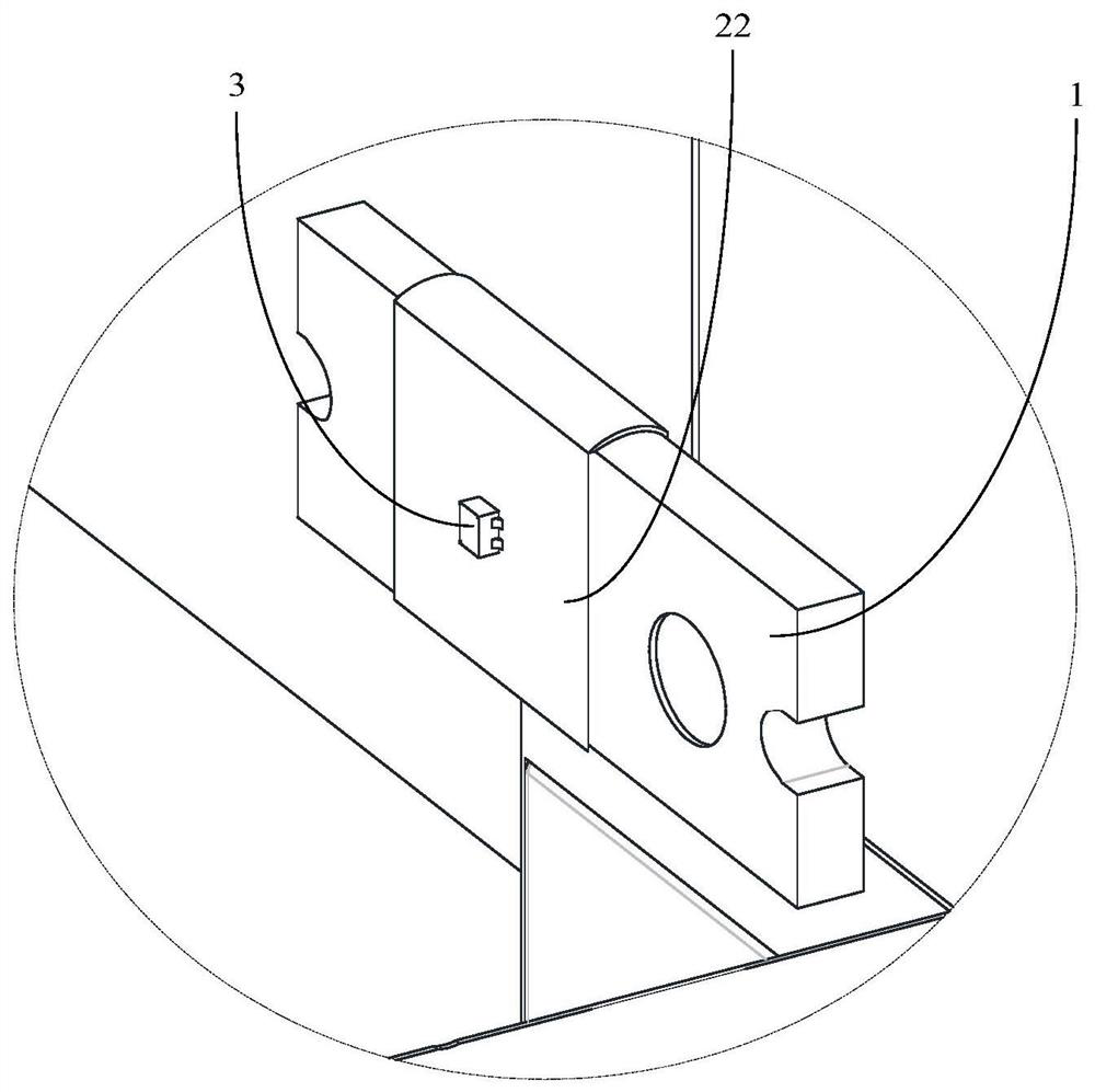
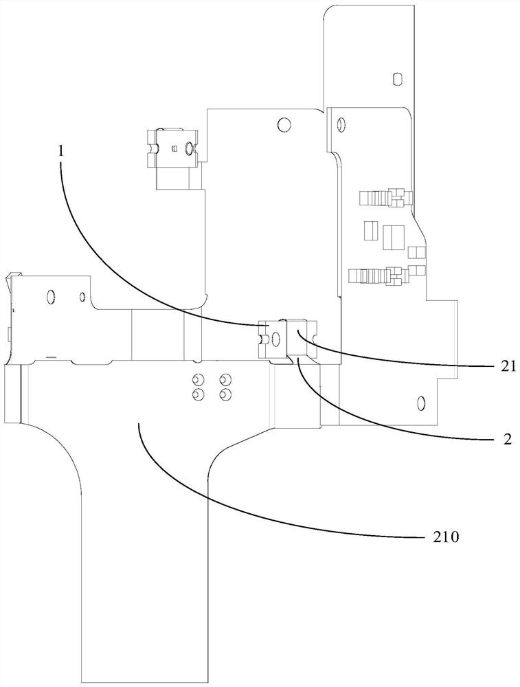
The invention discloses a displacement sensor circuit mounting structure, a zoom lens and an imaging device, the displacement sensor circuit mounting structure comprises a mounting plate, a flexible circuit board and a displacement sensor probe, the mounting plate is used for being mounted on a lens shell of the zoom lens, the mounting plate is provided with a mounting end face and a connecting end face which are oppositely distributed in the thickness direction of the mounting plate, the flexible circuit board comprises a first section attached to the connecting end face and a second section bent from the first section and then attached to the mounting end face, and the displacement sensor probe is attached to the end face, back to the mounting plate, of the second section. The displacement sensor probe is electrically connected to the flexible circuit board, the flexible circuit board is completely attached to the two end faces of the mounting plate, the flexible circuit board is prevented from being affected by external force, the flatness of the displacement sensor probe is prevented from being affected, meanwhile, the flatness of the displacement sensor probe can be adjusted through the mounting plate, and the displacement sensor probe can be fixed on the shell.

Description

technical field [0001] The invention relates to the technical field of optical imaging, in particular to a displacement sensor circuit installation structure, a zoom lens and an imaging device. Background technique [0002] The zoom lens includes a housing and a mobile carrier. The lens is set on the mobile carrier. In this way, the optical zoom is realized by the movement of the mobile carrier relative to the housing. At the same time, a displacement sensor is set to cooperate with the optical zoom. At present, the induction grid of the displacement sensor is usually installed on the mobile carrier. The sensor probe is usually installed on the flexible circuit board of the shell, but because the flexible circuit board is easily deformed by the external influence, the flatness of the displacement sensor probe cannot be guaranteed, so that the measurement results of the displacement sensor are prone to deviation. Contents of the invention [0003] The main purpose of the pr...

Claims


Application Information

Patent Timeline
IPC IPC(8): G02B7/28G03B13/34G01B11/02
CPCG01B11/02G02B7/28G03B13/34
Inventor 赵媚娇孔旭东郑旭东李昆吴恙吕强
Owner UNION OPTECH
Learn More