
High-precision chamfering machining die and method

A technology for processing molds and processing methods, used in forming tools, manufacturing tools, metal processing equipment, etc., can solve the problems of low chamfering efficiency, high positioning coordination requirements, low precision, etc., to eliminate errors, and process control is simple and efficient. Effect

Active Publication Date: 2021-06-08
珠海加特精密工业有限公司
View PDF7 Cites 0 Cited by
  • Summary
  • Abstract
  • Description
  • Claims
  • Application Information

AI Technical Summary

Problems solved by technology

[0004] The purpose of the present invention is to overcome the shortcomings of the above-mentioned prior art, provide a high-precision chamfering processing mold and method, and solve the problems of low efficiency, low precision, and cumbersome process in the prior art when processing chamfering of reinforcing plates , Overcoming the defect of high requirements for the positioning and coordination of the upper mold and the lower mold

Method used


Image

  • High-precision chamfering machining die and method
  • High-precision chamfering machining die and method
  • High-precision chamfering machining die and method

Examples


Embodiment 1

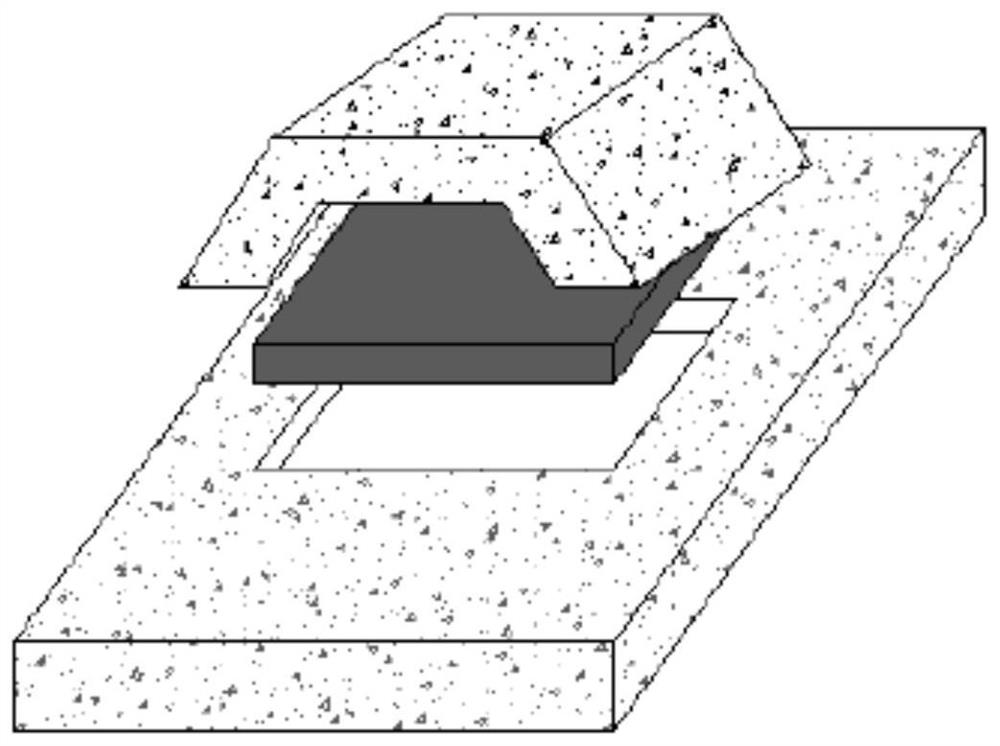
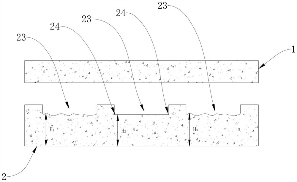
[0034] refer to Figure 2 to Figure 4 , the present embodiment provides a high-precision chamfering processing mold for forming chamfers on the reinforcing plate 3, including an upper mold 1 and a lower mold 2, the upper mold 1 includes a pressed flat plate 11, and the lower mold 2 includes at least one The concave molding cavity 23 is provided with a chamfering area 24 in the molding cavity 23, the molding cavity 23 is used for fixing and positioning the reinforcing plate 3, and the chamfering area 24 is used for pressing and positioning the pressing plate 11 in the molding cavity 23 When the reinforcing plate 3 is formed, chamfers are formed at the edges of the reinforcing plate 3 .

[0035] It should be noted that at least one molding cavity 23 is provided in the form of indentation on the upper surface of the lower mold 2, and a chamfering area 24 is processed in the molding cavity 23 by means of a spherical milling cutter. This chamfering area 24 includes at least one R ...

Embodiment 2

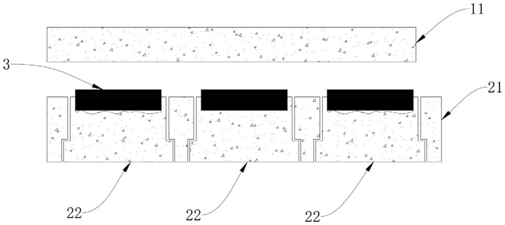
[0043] refer to figure 2 , the present embodiment 2 provides a method applied to high-precision chamfering processing molds in embodiment 1, comprising the following steps:

[0044] S1: Fix several inserts 22 to the lower mold base 21 respectively;

[0045] S2: Put the reinforcing plate 3 in the forming cavity 23 of the insert 22, align the edge of the reinforcing plate 3 to be chamfered with the chamfering area 24 in the forming cavity 23;

[0046] S3: Control the pressing flat plate 11 of the upper mold 1 to press down the reinforcing plate 3 to make the reinforcing plate 3 be chamfered and formed.

[0047] It should be noted that, in step S1, after placing several inserts 22 into the lower mold base 21, the flatness of the bottom surface of the molding cavity 23 is measured and adjusted. If the flatness of the bottom surface of each molding cavity 23 is high, no adjustment is required. If there is a difference in flatness between the molding cavities 23 between different...


PUM


Abstract

The invention provides a high-precision chamfering machining die and method, which are used for forming chamfers on reinforcing plates. The die comprises an upper die and a lower die, the upper die comprises a press-fit flat plate, the lower die comprises at least one concave forming cavity, a chamfering area is arranged in each forming cavity, each forming cavity is used for fixing and positioning the corresponding reinforcing plate, the chamfering areas are used for forming the chamfers at the edges of the reinforcing plates when the press-fit flat plate presses the reinforcing plates positioned in the corresponding forming cavities, and the lower die comprises a lower die base and a plurality of insert cores. The positioning requirement and the chamfering requirement are met through the forming cavities of the lower die, the chamfers are formed at the edges of the reinforcing plates through downward pressing of the upper die comprising the press-fit flat plate, the positioning requirement of the upper die and the lower die in the chamfering machining process is not high, fine debugging of the upper die and the lower die is not needed, the chamfering effect of the reinforcing plates is guaranteed, machining control is simple and efficient, and the insert cores are in clearance fit with the lower die base, so that the flatness of the bottom surfaces of the forming cavities is convenient to adjust, and the accuracy of chamfering machining of a plurality of reinforcing plates at the same time is ensured.

Description

technical field [0001] The invention belongs to the technical field of precision processing, and in particular relates to a high-precision chamfering processing mold and method. Background technique [0002] In the FPC flexible circuit board industry, the flexible board has high flexibility, but its strength is insufficient. To address this shortcoming, it is necessary to add a reinforcing board to a special part of the flexible board to strengthen the structural strength of the flexible board. In order to ensure the strengthening effect and prevent the burrs on the edge of the stiffener from piercing the soft board and affecting the circuit performance of the soft board, it is necessary to chamfer the edge of the stiffener. [0003] In the prior art, only a single reinforcing plate can be chamfered at one time, and the work efficiency is low. Moreover, due to the small size of the reinforcing plate, the chamfering size is smaller, which requires high flatness of the mold, a...

Claims


Application Information

Patent Timeline
Patent Type & Authority Applications(China)
IPC IPC(8): B21D19/08B21D37/10
CPCB21D19/08B21D37/10
Inventor 何军李求华李涛
Owner 珠海加特精密工业有限公司
Learn More