
Chamfering equipment for gear machining

A gear and chamfering technology, which is applied in the direction of metal processing equipment, mechanical equipment, components with teeth, etc., to achieve the effect of ensuring the quality of grinding, ensuring the quality of chamfering, and easy collection

Pending Publication Date: 2021-09-21
黄广华
View PDF0 Cites 0 Cited by
  • Summary
  • Abstract
  • Description
  • Claims
  • Application Information

AI Technical Summary

Problems solved by technology

[0004] The object of the present invention is to provide a kind of chamfering equipment for gear processing, to solve the problems of the prior art shortcomings in the above-mentioned background technology

Method used


Image

  • Chamfering equipment for gear machining
  • Chamfering equipment for gear machining
  • Chamfering equipment for gear machining

Examples


Embodiment Construction

[0028] The following will clearly and completely describe the technical solutions in the embodiments of the present invention with reference to the accompanying drawings in the embodiments of the present invention. Obviously, the described embodiments are only some, not all, embodiments of the present invention. Based on the embodiments of the present invention, all other embodiments obtained by persons of ordinary skill in the art without creative efforts fall within the protection scope of the present invention.

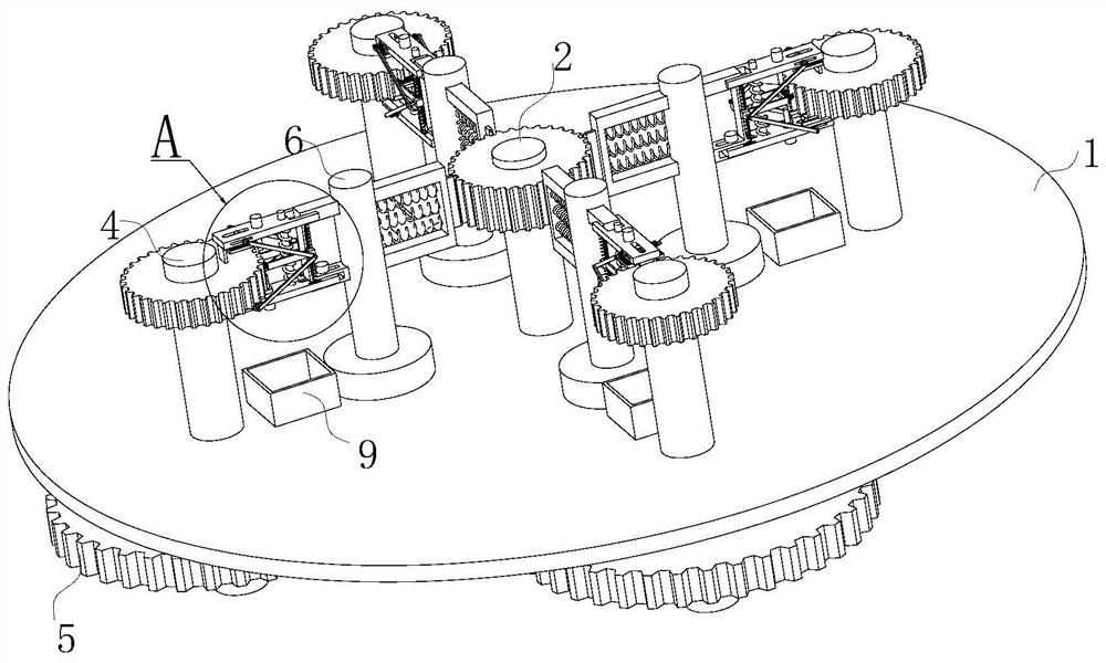
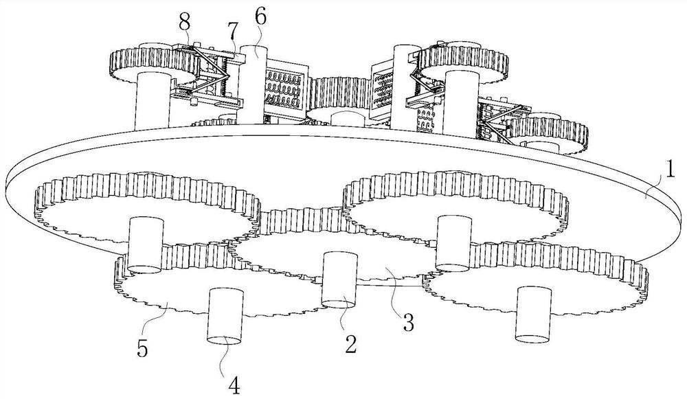
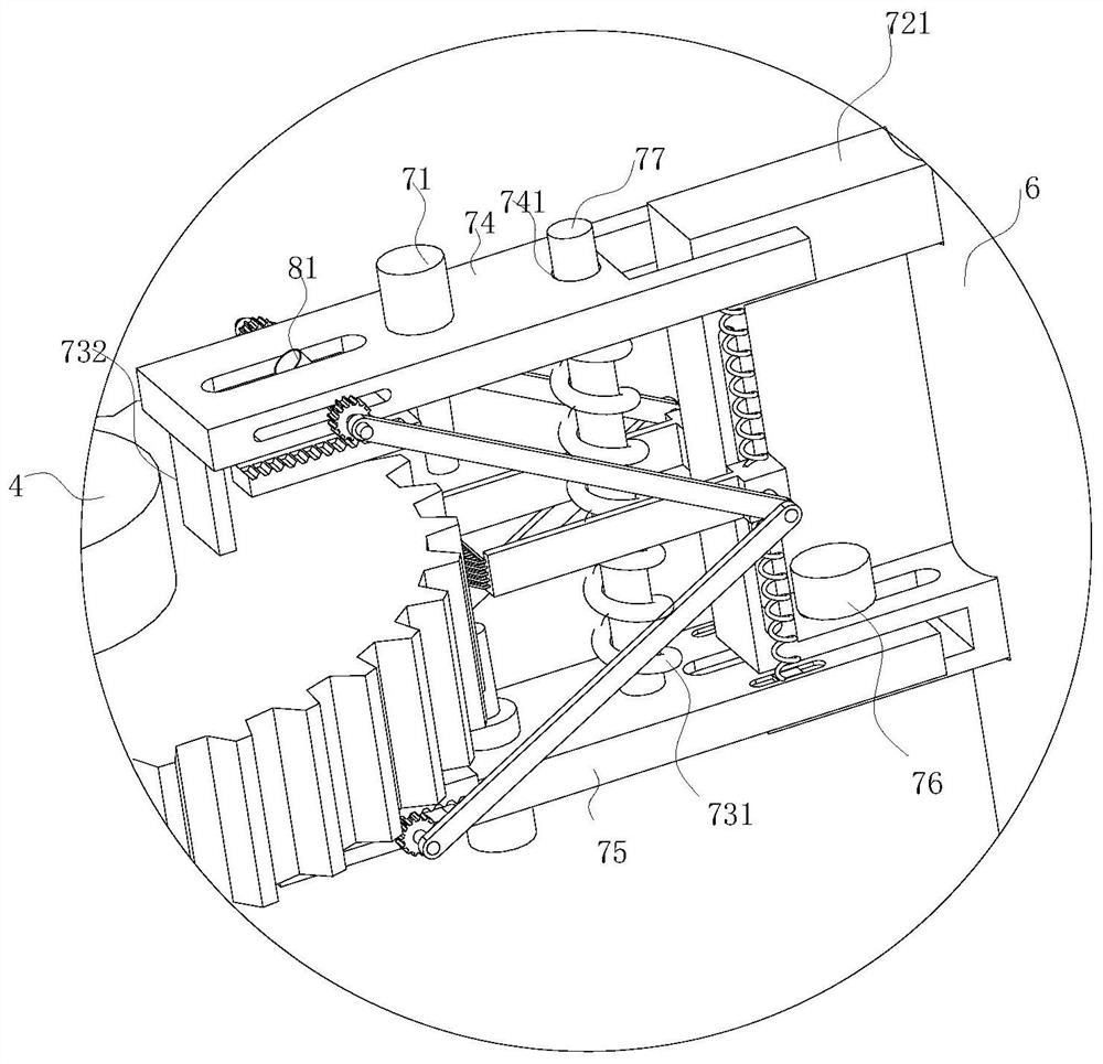
[0029] see Figure 1-8 , a kind of chamfering equipment for gear processing, including a disc-shaped workbench 1, a driving shaft 2 on which a mold gear is placed is rotatably installed on the central axis of the workbench 1, and an external driving source is fixedly installed on the driving shaft 2 The driving gear 3 is provided with a driven shaft 4 on the outer side of the driving shaft 2 at intervals to place the gear to be processed. The driven shaft 4 is rota...


PUM


Abstract

The invention discloses chamfering equipment for gear machining in the field of gear production. The chamfering equipment comprises a disc-shaped workbench, a driving rotating shaft is rotatably mounted on the central axis of the workbench, a driving gear is fixedly mounted on the driving rotating shaft, and driven rotating shafts for containing gears to be machined are arranged on the outer side of the driving rotating shaft in the circumferential direction at intervals; driven gears are rotationally mounted on the workbench, the driven gears are fixedly mounted on the driven rotating shafts, the driving gear is meshed with the driven gears, working columns are arranged between the driving rotating shaft and the driven rotating shafts, and the working columns are rotationally installed on the workbench; and the working columns are provided with chamfering mechanisms for chamfering the tooth profiles of the upper end faces and the lower end faces of the gears to be machined simultaneously. The chamfering equipment can automatically measure the thickness of the gears to be machined when chamfering the upper end faces and the lower end faces of the gears, and automatically adjust the inclination angles of water spraying units according to the thickness so that grinding scraps on the upper end faces can be stably stored in collecting boxes, grinding wheels on the lower portions are not affected, and the chamfering effect is guaranteed.

Description

technical field [0001] The invention belongs to the field of gear production, and in particular relates to a chamfering device for gear processing. Background technique [0002] Gears refer to mechanical elements with gears on the rim that continuously mesh to transmit motion and power, and are widely used in production. In the production process of the gear, it is necessary to chamfer the tooth profile of the end face of the gear. The chamfering can prevent the edge of the gear from protruding due to collision during the transmission process, can prevent the front from hurting people, and can switch between gears to make the connection smooth. However, the existing gear chamfering technology has the following disadvantages: 1. The existing CNC machine tool can only chamfer a single gear at a time, and the equipment cost is high and the processing efficiency is low; 2. The existing CNC machine tool is chamfering the gear. When chamfering, only one end face can be chamfered...

Claims


Application Information

Patent Timeline
Patent Type & Authority Applications(China)
IPC IPC(8): B23F19/12B23F23/00B23F23/06B23F23/12B23Q11/00
CPCB23F19/12B23F23/00B23F23/06B23F23/12B23Q11/0042B23Q11/0067
Inventor 黄广华
Owner 黄广华
Learn More