Connector

a technology of connecting rods and connectors, applied in the direction of air-flow influencers, branching pipes, transportation and packaging, etc., can solve the problems of affecting the performance of the connector, the risk of electrostatic build-up within the fsd being discharged through sparking, and the inability to easily remove and replace the connectors, etc., to achieve the optimum strength and durability of the assembly, and save production time

Pending Publication Date: 2020-01-09
AIRBUS OPERATIONS LTD
View PDF6 Cites 7 Cited by
  • Summary
  • Abstract
  • Description
  • Claims
  • Application Information

AI Technical Summary

Benefits of technology

[0010]The connector may be attachable to the panel by fasteners passing through the flanges. This arrangement provides the advantage that the connector may be easily removed from the aircraft panel if damaged. In addition, the fasteners will not intrude into the duct which would impede fluid flow within the duct.
[0014]At least one web may have a pillared structure with provision for fasteners between pillars. This arrangement provides structural rigidity to the connector with the fasteners being positioned between pillars and therefore taking up minimal space.
[0016]The assembly may include a reinforcing saddle interposed between the duct and connector, the saddle being permanently bonded to the duct. The duct and saddle may both comprise CFRP material and the saddle may be co-cured with the duct for saving on production time, optimum strength and durability of the assembly.
[0017]The saddle may have flanges adapted to engage the flanges of the connector, The saddle and connector may each have a hat cross section defining a generally flat crown, said crown defining the aperture, and in which sacrificial material may be provided between the crowns of the connector and saddle and between the flanges of the connector and saddle, said sacrificial material being removable as required to ensure a separation between the flanges and crown of the saddle measured in a direction normal to the flanges accurately matches such a distance between the flanges and crown of the connector.

Problems solved by technology

Such flow disruption results in pressure losses in the venting system.
Intrusion of fasteners can also lead to the risk of electrostatic build up within the FSD being discharged through sparking.
However, the use of such a bonded connection between the connector and FSD means that, if damaged, the connector cannot easily be removed and replaced.
Such connectors, because they sit proud of the FSD, are liable to damage.
A further difficulty with attachment of pipe connectors to FSDs is that the most convenient manner in which to make the fluid connection is normally through an aperture in a crown of the FSD.
However, the web of the FSD is generally not as wide as the crown which makes attachment of pipework of sufficient diameter to the web difficult.

Method used


Image

  • Connector
  • Connector
  • Connector

Examples


Embodiment Construction

[0043]Throughout the drawings, like features will where convenient be given the same reference numerals, for ease of understanding.

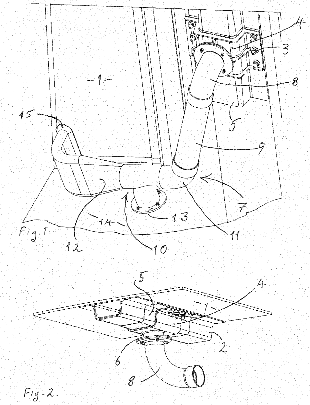
[0044]With reference to FIGS. 1 and 2 of the drawings, an aircraft fuel breather system is shown. The system includes an aircraft skin panel or cover 1 of CFRP material to which is attached by co-curing a hat section stringer in the form of a CFRP FSD 2. Attached to the cover 1 and FSD 2 by fasteners 3 is a connector 4. Between the FSD 2 and connector 4 is interposed a CFRP reinforcing saddle 5 which has been co-cured with the cover 1 and FSD 2.

[0045]Attached to the connector 4 via a flow controller connector in the form of a pipe connector 6 (see FIG. 2) is a fuel breather pipe shown generally as 7. The pipe 7 is made up of a flow controller in the form of an elbow connector 8 connected to a straight floating pipe 9 via an internal seal (not shown) and thence via a second floating internal seal (not shown) to a transition pipe 10. The transition pipe 10...


PUM


Abstract

A connector, a connector assembly, an aircraft fuel breather system and an aircraft wing are disclosed. The connector connects a breather pipe or float valve to a hat section stringer duct attached to an aircraft panel. The connecter has a bridge to bridge over the duct and to cover an aperture in a wall of the duct. The bridge has a flange on either side for attachment of the connector to the panel. The connector has a seal to seal the bridge to the duct, an aperture defined in the bridge and a flow controller connector to connect and provide fluid connection between the connector and pipe or float valve. The assembly comprises the connector, the duct and aircraft panel and the fuel breather system includes one or more fuel tanks, a breather pipe and a vent to atmosphere.

Description

FIELD OF THE INVENTION[0001]The present invention relates to a connector for connecting an aircraft stringer duct to a pipe or other type of flow controller. In particular, the invention relates to such a connector which is capable of being releasably attached to the duct without penetrating the interior of the duct.BACKGROUND[0002]It is known to use aircraft hat section wing stringers as ducts to conduct fluids as both liquids and gasses spanwise of the wing. Stringers are stiffening members firmly attached to the skin, otherwise known as the cover, of the wing. They run spanwise of the wing, from wing root to wing tip. The cross-sectional shape of a hat stringer is defined by two spaced co-planar flanges for attachment of the stringer to a panel being stiffened, a pair of spaced upstanding webs attached to inner edges of the flanges and a crown bridging across distal edges of the webs. Such a stringer, when attached to a panel being stiffened, forms a closed channel which is capab...

Claims


Application Information

Patent Timeline
Patent Type & Authority Applications(United States)
IPC IPC(8): B64C23/00B64C3/38B64C3/20B64C3/26
CPCB64C3/38B64C3/20B64C23/005B64C3/26F16L41/08B64C1/064B64D37/005B64C3/34B64C3/182F16L41/082F16L41/021
Inventor DOUGLAS, PAULBRYANT, ANTHONY JOHNPEACHEY, DANIEL
Owner AIRBUS OPERATIONS LTD
Why Eureka
Try Eureka