Double-sided chamfering tool

A technology of chamfering tool and chamfering tool, which is applied in milling cutters, manufacturing tools, metal processing equipment, etc., can solve the problems of low chamfering efficiency, poor chamfering effect, unfavorable chamfering consistency, etc., to increase chamfering Efficiency, the effect of ensuring the chamfering effect

Pending Publication Date: 2022-03-25
CHENGDU SIWI HIGH TECH IND GARDEN
View PDF0 Cites 0 Cited by
  • Summary
  • Abstract
  • Description
  • Claims
  • Application Information

AI Technical Summary

Problems solved by technology

The existing chamfering methods mainly include two types: the first method is manual chamfering, that is, the fitter uses a drill to perform chamfering, the chamfering effect is poor and the efficiency is low, and it is suitable for occasions with low requirements; the second method is through chamfering Corner knife combined with programming for chamfering, this method has relatively high accuracy and efficiency
[0003] However, both methods require secondary chamfering, that is, after the operator completes one side, he needs to turn the workpiece over and perform chamfering again, which is unfavorable for the consistency of chamfering; The position of the clamp is offset from the position of the last clamping, which needs to be programmed again, which will undoubtedly cause low chamfering efficiency

Method used


Image

  • Double-sided chamfering tool
  • Double-sided chamfering tool
  • Double-sided chamfering tool

Examples


Embodiment Construction

[0039] Below in conjunction with accompanying drawing, the present invention is described in detail.

[0040] In order to make the object, technical solution and advantages of the present invention clearer, the present invention will be further described in detail below in conjunction with the accompanying drawings and embodiments. It should be understood that the specific embodiments described here are only used to explain the present invention, not to limit the present invention.

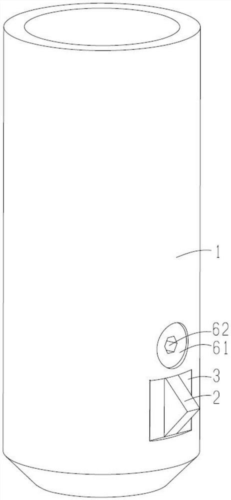
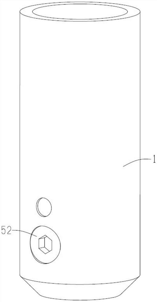
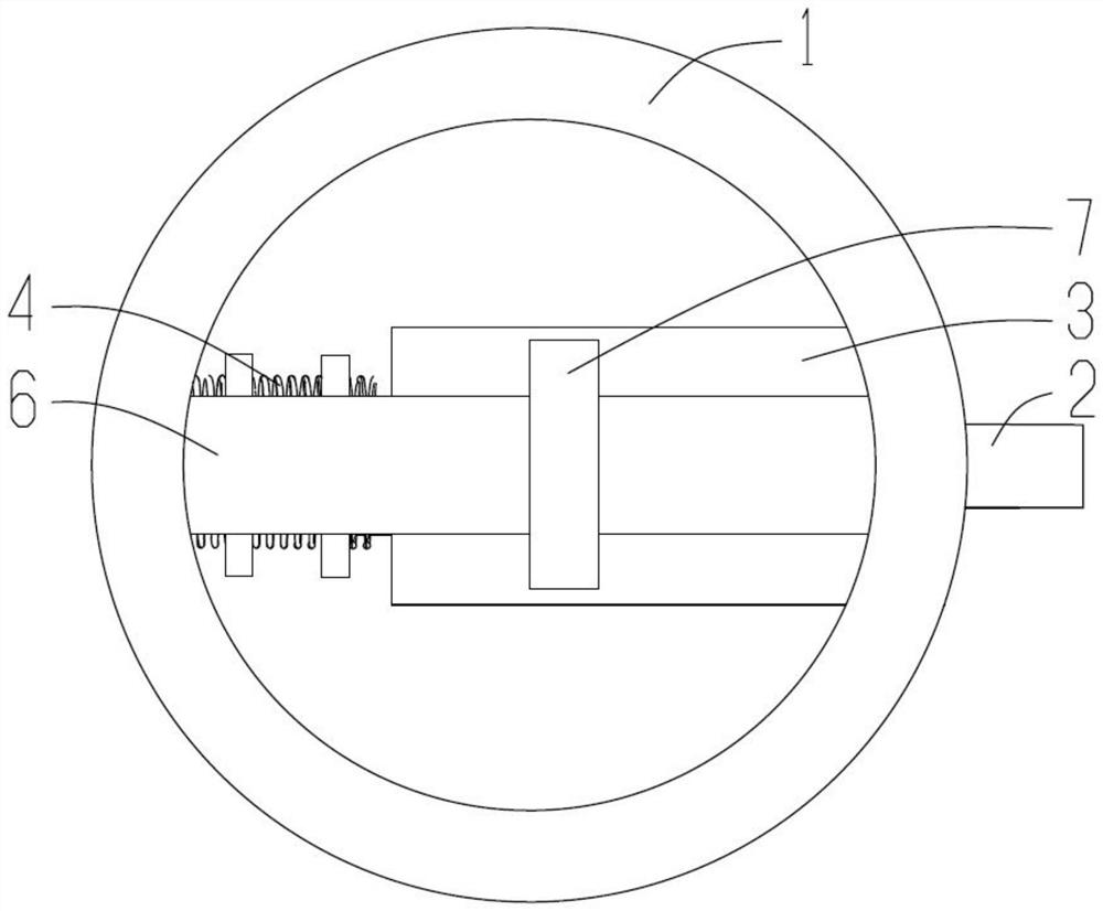
[0041] Please see Figure 1 to Figure 11 , a double-sided chamfering tool installed on the shank of a CNC milling tool, the following description will be made by taking a CNC milling machine with the tool bar vertically facing down as an example.

[0042] The double-sided chamfering tool includes a tool bar 1, a chamfering knife 2, a centrifugal block 3, an elastic piece 4, a mounting piece 5, an adjusting rod 6, and an adjusting ring 7. The knife bar 1 is arranged vertically and is cylindrical,...


PUM


Abstract

The invention discloses a double-sided chamfering cutter, and relates to the technical field of mechanical milling machining cutters, the double-sided chamfering cutter comprises a cutter bar, a cutter hole is formed in the side wall of the cutter bar, an elastic piece is fixed in the cutter hole, a chamfering cutter is fixed on the elastic piece, the chamfering cutter has at least two cutting edges, and the directions of the at least two cutting edges are opposite; the moving direction of the elastic piece is perpendicular to the rotating shaft of the cutter bar. The direction of at least one cutting edge of the chamfering cutter is opposite to that of a cutting edge of a common cutter for numerical control milling, and the cutting edge can chamfer the back face of a workpiece. When the cutter bar does not rotate, the chamfering cutter retracts into the cutter hole, so that other parts of the workpiece cannot be damaged by the chamfering cutter in the moving process of the cutter bar, and when the cutter bar moves to a to-be-chamfered position on the back surface of the workpiece, the cutter bar rotates to generate centrifugal force, so that the elastic piece drives the chamfering cutter to extend out of the cutter hole and protrude out of the cutter bar; and chamfering the corresponding position of the back surface of the workpiece.

Description

technical field [0001] The invention relates to the technical field of mechanical milling tools, in particular to a double-sided chamfering tool. Background technique [0002] In milling, chamfering is one of the more common processing techniques. The existing chamfering methods mainly include two types: the first method is manual chamfering, that is, the fitter uses a drill to perform chamfering, the chamfering effect is poor and the efficiency is low, and it is suitable for occasions with low requirements; the second method is through chamfering The corner knife is combined with programming for chamfering, which has relatively high accuracy and efficiency. [0003] However, both methods require secondary chamfering, that is, after the operator completes one side, he needs to turn the workpiece over and perform chamfering again, which is unfavorable for the consistency of chamfering; The position of the clamp is offset from the position of the last clamping, which needs t...

Claims


Application Information

Patent Timeline
Patent Type & Authority Applications(China)
IPC IPC(8): B23C5/24B23C5/02
CPCB23C5/2465B23C5/02B23C2220/16B23C2270/04
Inventor 徐韶华张邦平向玫尹晓华陈静刘静
Owner CHENGDU SIWI HIGH TECH IND GARDEN
Why Eureka
Try Eureka