Metal flange plate machining equipment for pipe fitting connection

A processing equipment and metal technology, which is applied in the field of metal flange processing equipment for pipe fittings, can solve the problems of difficult grinding and slow efficiency, and achieve the effect of facilitating drilling and chamfering

Pending Publication Date: 2021-03-12
张俊港
View PDF9 Cites 0 Cited by
  • Summary
  • Abstract
  • Description
  • Claims
  • Application Information

AI Technical Summary

Problems solved by technology

[0004] In order to overcome the disadvantages that the efficiency of manual drilling is slow, and that it is not easy to grind all the edges of the drilled holes manually, the technical problem to be solved is to provide a method that can automatically drill holes on the flange, and when the drilling is completed, Afterwards, the edge of the drilled hole can be polished and smooth, and the metal flange processing equipment for the connection of the pipe fittings can be used.

Method used


Image

  • Metal flange plate machining equipment for pipe fitting connection
  • Metal flange plate machining equipment for pipe fitting connection
  • Metal flange plate machining equipment for pipe fitting connection

Examples


Embodiment 1

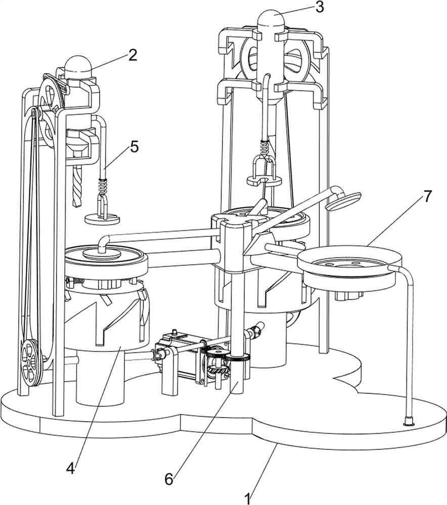
[0064] A metal flange processing equipment for pipe fittings, such as figure 1 As shown, a base plate 1, a punching mechanism 2 and a chamfering mechanism 3 are included, the punching mechanism 2 is provided on the top left side of the base plate 1, and the chamfering mechanism 3 is provided on the top right side of the base plate 1.

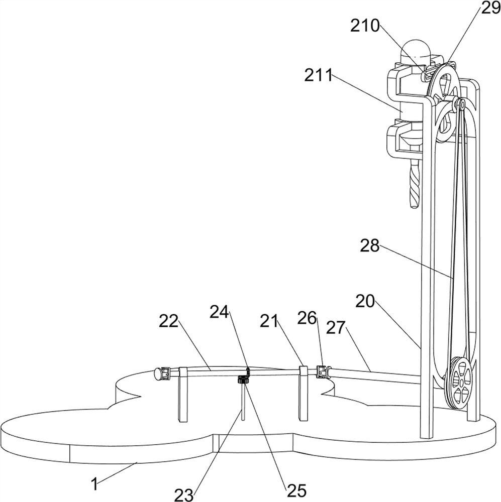
[0065] Such as figure 2As shown, the punching mechanism 2 includes a first support frame 20, a bearing seat 21, a first rotating shaft 22, a second rotating shaft 23, a bevel gear 24, a first gear 25, a universal joint 26, a third rotating shaft 27, a first Pulley group 28, first turntable 29, first slide rail 210 and puncher 211, base plate 1 top left side is provided with first support frame 20, and base plate 1 top center left and right symmetrically is provided with bearing seat 21, between bearing seat 21 Connected with the first rotating shaft 22, the bottom plate 1 is provided with a second rotating shaft 23 in the middle of the rotatio...

Embodiment 2

[0069] On the basis of Example 1, such as Figure 4 As shown, a rotating mechanism 4 is also included, and the rotating mechanism 4 includes a mounting column 40, a sheave 41, a push rod 42, a limit rod 43, a first spring member 44 and a clip 45, and the left and right sides of the top of the base plate 1 are provided with Mounting post 40 is arranged, and the third rotating shaft 27 and the fourth rotating shaft 31 are all rotatably matched with the mounting post 40, and the mounting post 40 is provided with a sheave 41 in a rotating manner, and the puncher 211 and the chamfering device 35 are provided with pushers. Rod 42, push rod 42 cooperates with sheave 41, and the left and right sides of sheave 41 top all slides and is provided with limit bar 43, and the inside of limit bar 43 is all provided with clip block 45, between clip block 45 and sheave 41 A first spring element 44 is attached.

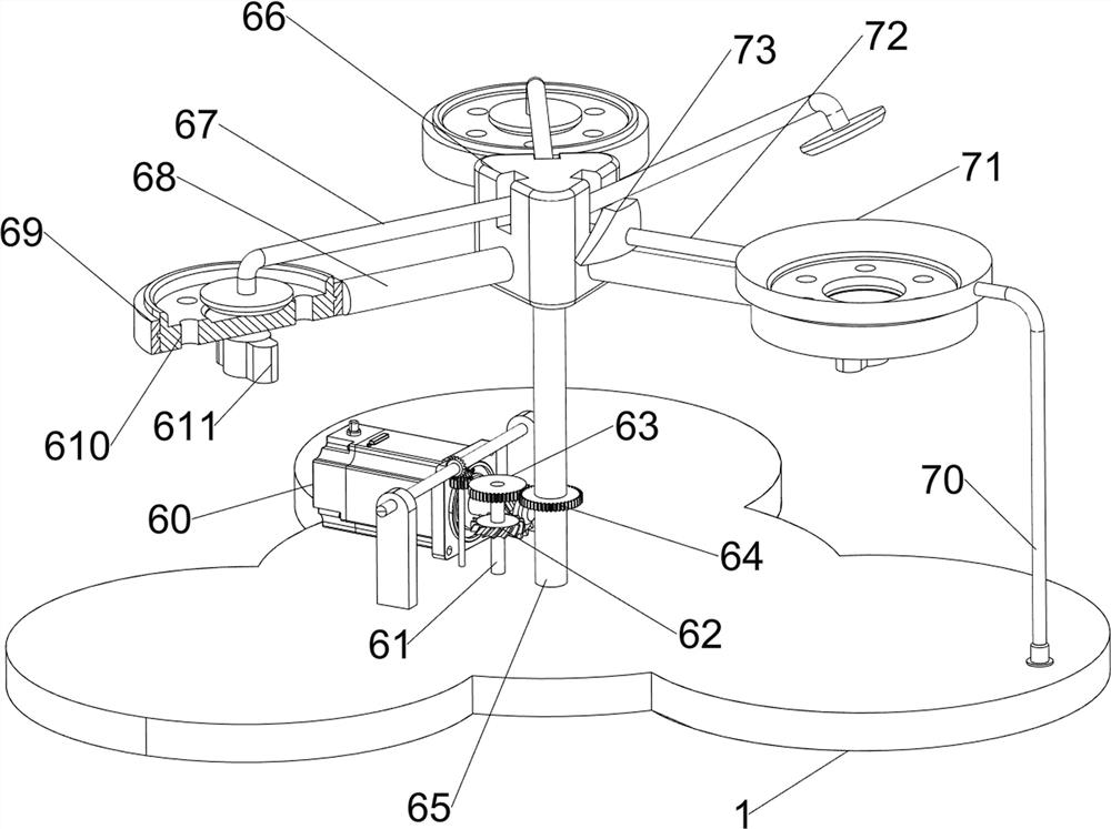
[0070] Such as Figure 5 Shown, also comprise rotating mechanism 6, and rotating ...


PUM


Abstract

The invention relates to machining equipment, in particular to metal flange plate machining equipment for pipe fitting connection. According to the metal flange plate machining equipment for pipe fitting connection, a flange plate can be automatically punched, and the edge of a punched hole can be polished to be smooth after punching is completed. According to the technical scheme, the metal flange plate machining equipment for pipe fitting connection comprises a bottom plate and a chamfering mechanism, and a punching mechanism is arranged on one side of the top of the bottom plate; and the chamfering mechanism is arranged on the other side of the top of the bottom plate. After the flange plate is placed by a worker through the punching mechanism, a first rotating shaft is controlled to rotate, and then the flange plate can be drilled; and the drilled hole can be chamfered through the arranged chamfering mechanism, so that the edge position of the drilled hole becomes smooth to facilitate pipe fitting connection work.

Description

technical field [0001] The invention relates to a processing device, in particular to a metal flange processing device for connecting pipe fittings. Background technique [0002] The flange is a part that connects the pipes with each other. It is easy to use and has high practicability. During the processing of the flange, it needs to be drilled. After the hole is finished, the edge of the hole needs to be drilled. Grinding to make it smooth is currently done manually. After the flange is placed, a drilling machine is used to drill holes in the flange. The edge of the perforated part is manually polished with an abrasive tool to make it smooth, but because the hole is usually circular during manual grinding, the inside is difficult to be polished, thus affecting the normal use of the iron plate. [0003] Therefore need to design a kind of can be automatically punched to flange plate, after punching completes, also can polish the smooth pipe fitting connection metal flange p...

Claims


Application Information

Patent Timeline
Patent Type & Authority Applications(China)
IPC IPC(8): B23P23/04
CPCB23P23/04
Inventor 张俊港
Owner 张俊港
Why Eureka
Try Eureka