Material cutting device for construction site construction

A technology for construction sites and cutting devices, used in metal processing, manufacturing tools, metal processing equipment, etc., can solve the problems of troublesome tool change, pollution, low cutting efficiency, etc., and achieve the effects of simple and convenient control, convenient use and novel design

Active Publication Date: 2019-04-09
HUNAN INST OF TECH
View PDF9 Cites 1 Cited by
  • Summary
  • Abstract
  • Description
  • Claims
  • Application Information

AI Technical Summary

Problems solved by technology

[0003] When the current cutting machine is working, the operator first needs to place the material to be cut above the machine tool, and after the material is placed in a suitable position, the cutting wheel is aligned with the object to be cut for cutting. The material is removed from the cutting machine. This operation method may cause the operator to be injured by the cutting wheel of the cutting machine, causing danger. As a result, the cutting efficiency is also very low. Moreover, for the construction of building materials, such as plates, etc., it is generally necessary to chamfer it. It is difficult for the current common cutting equipment to complete the chamfering process, especially when the chamfering is completed at the same time. There are fewer and fewer equipments for corners, and the current chamfering equipment generally uses chamfering tools for chamfering, which leads to more knives, troublesome changing of knives, and affects construction efficiency. Cutting equipment with low coefficient and good environmental protection effect

Method used


Image

  • Material cutting device for construction site construction
  • Material cutting device for construction site construction
  • Material cutting device for construction site construction

Examples


Embodiment Construction

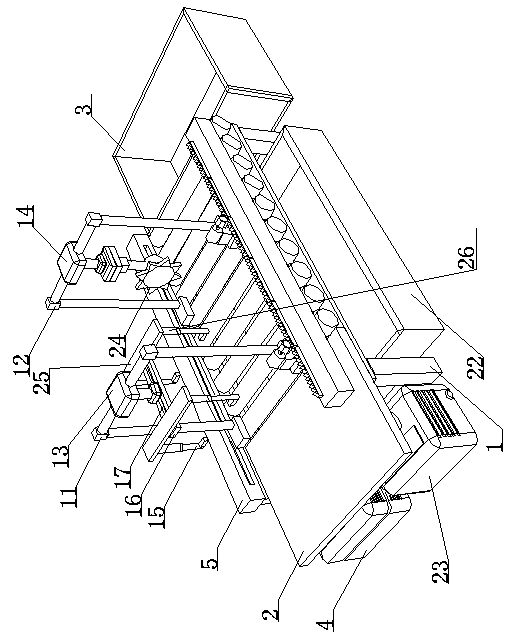
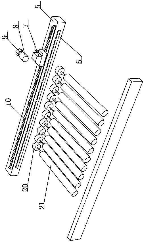
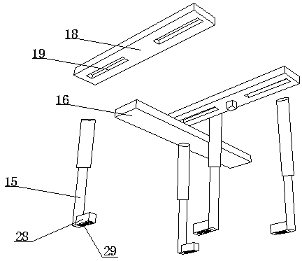
[0025] see Figure 1~5 , in an embodiment of the present invention, a construction site construction material cutting device includes a frame 1, a feed plate 2 is provided on the left side of the frame 1, and a collecting box is provided on the right side of the frame 1 3. The upper end of the feed plate 2 is used to place the building construction materials that need to be cut. The right side of the frame 1 is provided with a collection box 3. The cut materials are stored in the collection box 3, which is convenient for the operator to take out uniformly. The lower side of the feed plate 2 is provided with a power supply 4, which can provide the cutting equipment with the required electric energy. The frame is located between the feed plate 2 and the collection box 3, and is provided with a cutting assembly and a grabbing positioning assembly that can slide left and right. The frame is located between the feed plate 2 and the collection box A transmission assembly is also ar...


PUM


Abstract

The invention discloses a material cutting device for construction site construction and relates to the technical field of construction site construction. A cutting component can carry out chamferingoperation on to-be-cut material; and during the chamfering operation process, a grabbing positioning component can grab the to-be-cut material and keeps the to-be-cut material inclined according to aneeded chamfering angle to realize chamfering cutting treatment of the to-be-cut material through vertically downward cutting of the cutting component. The material cutting device is novel in design,simple in structure and convenient to use, adjusts the transverse distance between mechanical arms according to the width of the material and also adjusts the longitudinal distance between mechanicalarms according to the length of the material to precisely grab the material; during the process, manual grabbing of the material is not needed to prevent the cutting device from accidentally hurting an operator, sweeps can leak in waste box from gaps of transmission rods to prevent environmental pollution caused by falling of the sweeps on the ground.

Description

technical field [0001] The invention relates to the technical field of construction site construction, in particular to a material cutting device for construction site construction. Background technique [0002] When carrying out construction on a construction site, it is necessary to use a cutting machine to cut steel bars, wood and other materials. With the development of the modern mechanical processing industry, the requirements for cutting quality and accuracy are continuously improved, which is very important for improving production efficiency and reducing production costs. , The requirements for highly intelligent automatic cutting functions are also increasing. Cutting machines are divided into flame cutting machines, plasma cutting machines, laser cutting machines, water cutting, etc. Laser cutting machines have the fastest efficiency, the highest cutting precision, and the cutting thickness is average. Smaller, the cutting speed of the plasma cutting machine is al...

Claims


Application Information

Patent Timeline
Patent Type & Authority Applications(China)
IPC IPC(8): B23D79/00B23Q7/00B23Q7/05B23Q11/00
CPCB23D79/00B23Q7/008B23Q7/055B23Q11/0067
Inventor 姜雨佳刘鑫侯宇飞
Owner HUNAN INST OF TECH
Why Eureka
Try Eureka