Pressure-accumulating jet system

A technology of injection system and pressure accumulation, applied in charging system, fuel injection device, fuel injection control, etc., can solve problems such as low fuel injection correction effect

Inactive Publication Date: 2009-06-10
DENSO CORP
View PDF4 Cites 0 Cited by
  • Summary
  • Abstract
  • Description
  • Claims
  • Application Information

AI Technical Summary

Problems solved by technology

Errors in the fuel supply pump assembly and the engine crankshaft cause the problem that even if the time overlap is known in advance from narrative, experiment or the like, the correction of fuel injection based on said time overlap has little effect

Method used


Image

  • Pressure-accumulating jet system
  • Pressure-accumulating jet system
  • Pressure-accumulating jet system

Examples


no. 1 example

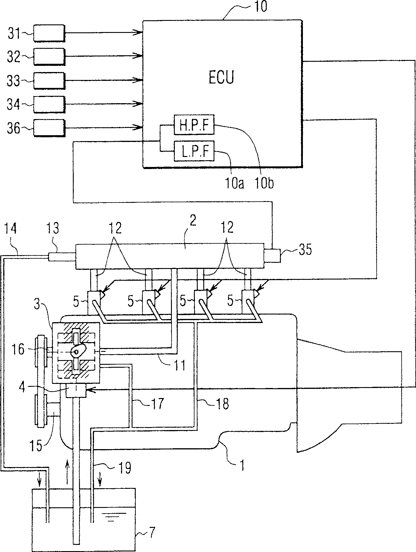
[0064] figure 1 ~4 shows a first embodiment of the invention, figure 1 is a block diagram showing a common rail fuel injection system.

[0065] A common rail fuel injection system is used on engines such as 4 cylinder diesel engines. The common rail fuel injection system includes a common rail 2 used as an accumulator, in which high-pressure fuel is accumulated to a pressure that is the same as a fuel injection pressure capable of injecting fuel into each cylinder. The common rail fuel injection system also has a fuel supply pump 3 for applying pressure to the absorbed fuel and then pumping the pressurized fuel into the common rail 2 . The common rail fuel injection system also has a plurality of electromagnetic fuel injection valves 5 for supplying high-pressure fuel stored in the common rail 2 into the cylinders of the engine 1 . Typically the engine 1 has 4 cylinders. The electromagnetic fuel injection valve 5 is hereinafter referred to as a nozzle. The common rail fue...

no. 2 example

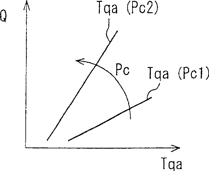
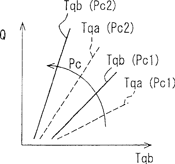
[0094] In the second embodiment, only one basic feature map is used. The basic characteristic map is used to find the first basic fuel injection duration Tqa for non-overlapping cylinders. Based on the actual time overlapping portion t, the first basic fuel injection duration Tqa is corrected to determine the second basic fuel injection duration Tqb of the overlapping cylinders.

[0095] More specifically, using a correction means for correcting the first basic fuel injection duration Tqa of non-overlapping cylinders, changing the first basic fuel injection duration Tqa and the second basic fuel injection duration Tqb of overlapping cylinders difference between, or using a correction means for correcting the second basic fuel injection duration Tqb, change the difference between the second basic fuel injection duration Tqb and the first basic fuel injection duration Tqa, thereby The second basic fuel injection duration Tqb is made shorter than the first basic fuel injection d...

no. 3 example

[0105] Figure 8-12 A third embodiment of the invention is shown, in which Figure 8 A flowchart showing a method of controlling fuel injection using a fuel injection valve. on the other hand, Figure 9 A flowchart of a method of finding temporal overlaps is shown. exist Figure 8 with 9 The routine represented by the flow chart shown in is repeatedly executed at a predetermined timing after the ignition switch is turned on.

[0106] Figure 8 The flow chart shown starts at step S31, where engine parameters are input. The engine parameters include engine speed NE and accelerator on ACCP. Then in step S32, the target fuel injection quantity Q is determined based on the engine speed NE and the acceleration-on ACCP. Then at step S33, the target fuel injection timing T is determined based on the engine speed NE and the accelerator-on ACCP. Then in step S34, the common rail fuel pressure Pc is input.

[0107] Then at step S35, the target fuel injection timing T is convert...


PUM


Abstract

The pressure is applied to the fuel filled in each air cylinder of an engine (1) by a fuel ejected valve (5) via a fuel feed pump (3). A engine control unit (10) sets a signal for driving the fuel ejected valve (5), such that the difference of the fuel ejected amount between both instances is prevented, wherein one instance is that, a pump feed duration of the fuel feed pump (3) and an ejecting duration of the fuel ejected valve (5) in air cylinder are overlapped, the other is that, a pump feed duration of the fuel feed pump (3) and an ejecting duration of the fuel ejected valve (5) in air cylinder are not overlapped. In the front instance, the time overlapped part is determined as a time when the pump feed duration and the fuel ejected duration are overlapped. If the time overlapped part is changed, the engine control unit (10) sets a signal for for driving the fuel ejected valve (5) based on the time overlapped part.

Description

technical field [0001] The present invention relates to an accumulator injection system for storing high-pressure fuel discharged by a fuel supply device such as a supply pump in an accumulator for supplying the high-pressure fuel accumulated in the accumulator to the In each cylinder of an internal combustion engine such as a multi-cylinder diesel engine. Background technique [0002] For a common fuel injection system for an internal combustion engine such as a multi-cylinder diesel engine, a known accumulator injection system includes a common rail, a plurality of fuel injection valves and a supply pump. The common rail is used as an accumulator for pressurizing fuel and storing high-pressure fuel at the pressure at which it is injected into cylinders of the engine. The fuel injection valve is an electromagnetic fuel injection valve installed on each cylinder of the engine. The supply pump is used as a fuel supply pump for applying pressure to the fuel that enters the p...

Claims


Application Information

Patent Timeline
Patent Type & Authority Patents(China)
IPC IPC(8): F02D41/40F02D41/38F02M39/02F02M63/02
CPCF02D41/40Y02T10/44F02M39/02F02D2041/225F02M63/0225F02D41/406F02D41/3845F02D2200/0602Y02T10/40
Inventor 中村兼仁
Owner DENSO CORP
Why Eureka
Try Eureka