Connector

A technology of connectors and through holes, applied in the direction of connection, fixed connection, contact parts, etc., can solve the problems of low production efficiency, achieve the effect of equal contact pressure and stable spring pressure

Inactive Publication Date: 2009-06-17
SMK CO LTD
View PDF5 Cites 4 Cited by
  • Summary
  • Abstract
  • Description
  • Claims
  • Application Information

AI Technical Summary

Problems solved by technology

[0010] Also, the shape of the connector 140 is asymmetrical up and down in the press-fitting direction. When actually installing a plurality of connectors into the through-hole 150, they must be pressed one by one after setting the direction, and the production efficiency is very low.

Method used


Image

  • Connector
  • Connector
  • Connector

Examples


Embodiment Construction

[0048] Figure 5 It is an embodiment of the connector of the present invention.

[0049] Figure 5 (1) is a top view, Figure 5 (2) is a bottom view, Figure 5 (3) is a side view.

[0050] In the connector 10 , a plurality of contacts 30 are arranged in the plane direction of the insulating layer 20 .

[0051] This connector 10 is used for example as an LGA socket in the Figure 5 On the surface shown in (2), an LGA-type LSI is mounted and connected to a printed circuit board.

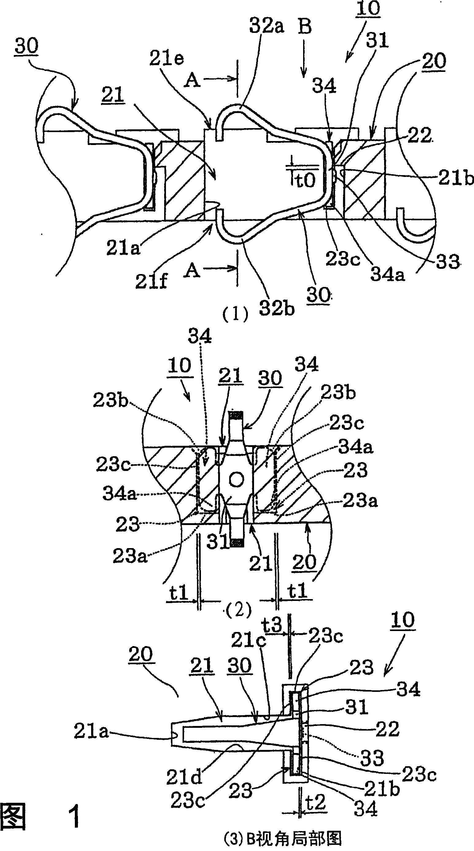
[0052] FIG. 1(1) is an enlarged schematic longitudinal section of the connector 10 near the joint 30, FIG. 1(2) shows a sectional view along line A-A, and FIG. 1(3) shows a partial view from a B perspective.

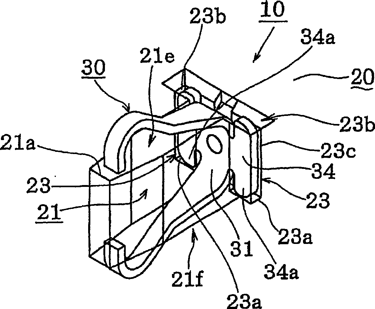
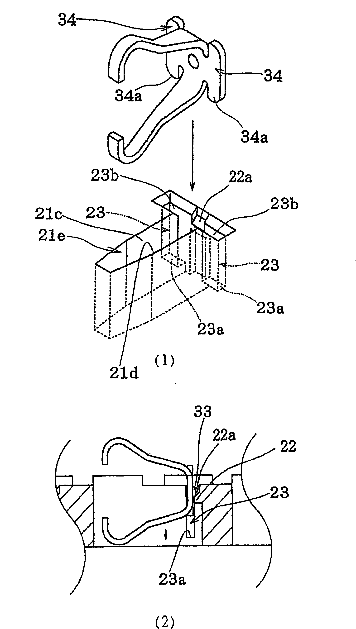
[0053] again, figure 2 It is a partial perspective view depicting the through hole 21 and the joint 30 through the insulating layer 20 .

[0054]The connector 10 is provided with a through-hole 21 penetrating through the insulating layer 20 in the thickness direction of the flat insulati...


PUM


Abstract

This invention relates to connector, which forms several through holes on insulation layers with contact points and which is characterized by the following: comprising base socket, one pair of contact part and protruding shoulder part and card block part; the through holes on the insulation layer has guide tank to contain joint and card block part of interference joint and block part for keep insulation layer free move along thickness direction.

Description

technical field [0001] The present invention relates to a connector. When LGA (Land Grid Array) type electronic parts and printed circuit boards, or printed circuit boards are mated and connected to each other, electrodes are connected by pressing and clamping the connector between them. mutual conduction. Background technique [0002] Conventionally, as an LGA-type electronic component, as a connector for connecting LSI (Large Scale Integration) or IC (Integrated Circuit Integrated Circuit) and electrode terminals of a printed circuit board, etc., there are Figure 6 , Figure 7 connector shown. [0003] Figure 6 connectors such as Figure 6 As shown in (1), the connector 110 is clamped between the electronic parts 101, 102, and the electronic parts 101, 102 are approached to each other, and as Figure 6 As shown in (2), the plurality of electrodes 101a, 102a of the two components are pressed into contact with the contact portions 132a, 132b of the connector 110, thereby ...

Claims


Application Information

Patent Timeline
Patent Type & Authority Patents(China)
IPC IPC(8): H01R12/22H01R12/36H01R13/24H01R13/42H01R12/71H01R12/57
Inventor 荒井厚菅野英雄
Owner SMK CO LTD
Why Eureka
Try Eureka