Low-gravity golf head structure

A golf club head and low center of gravity technology, applied to golf balls, golf clubs, rackets, etc., can solve the problems of reducing the weight of the front half of the club head and not being easy

Inactive Publication Date: 2009-06-24
NELSON PRECISION CASTING
View PDF7 Cites 0 Cited by
  • Summary
  • Abstract
  • Description
  • Claims
  • Application Information

AI Technical Summary

Problems solved by technology

In other words, it is not easy to significantly and relatively reduce the weight of the front half of the club head so as to contribute a large range of adjustment of the center of gravity under the premise that the striking panel is simply made of a light metal material.

Method used


Image

  • Low-gravity golf head structure
  • Low-gravity golf head structure
  • Low-gravity golf head structure

Examples


Embodiment Construction

[0029] In order to make the above and other objects, features and advantages of the present invention more comprehensible, preferred embodiments of the present invention will be exemplified below and described in detail with accompanying drawings.

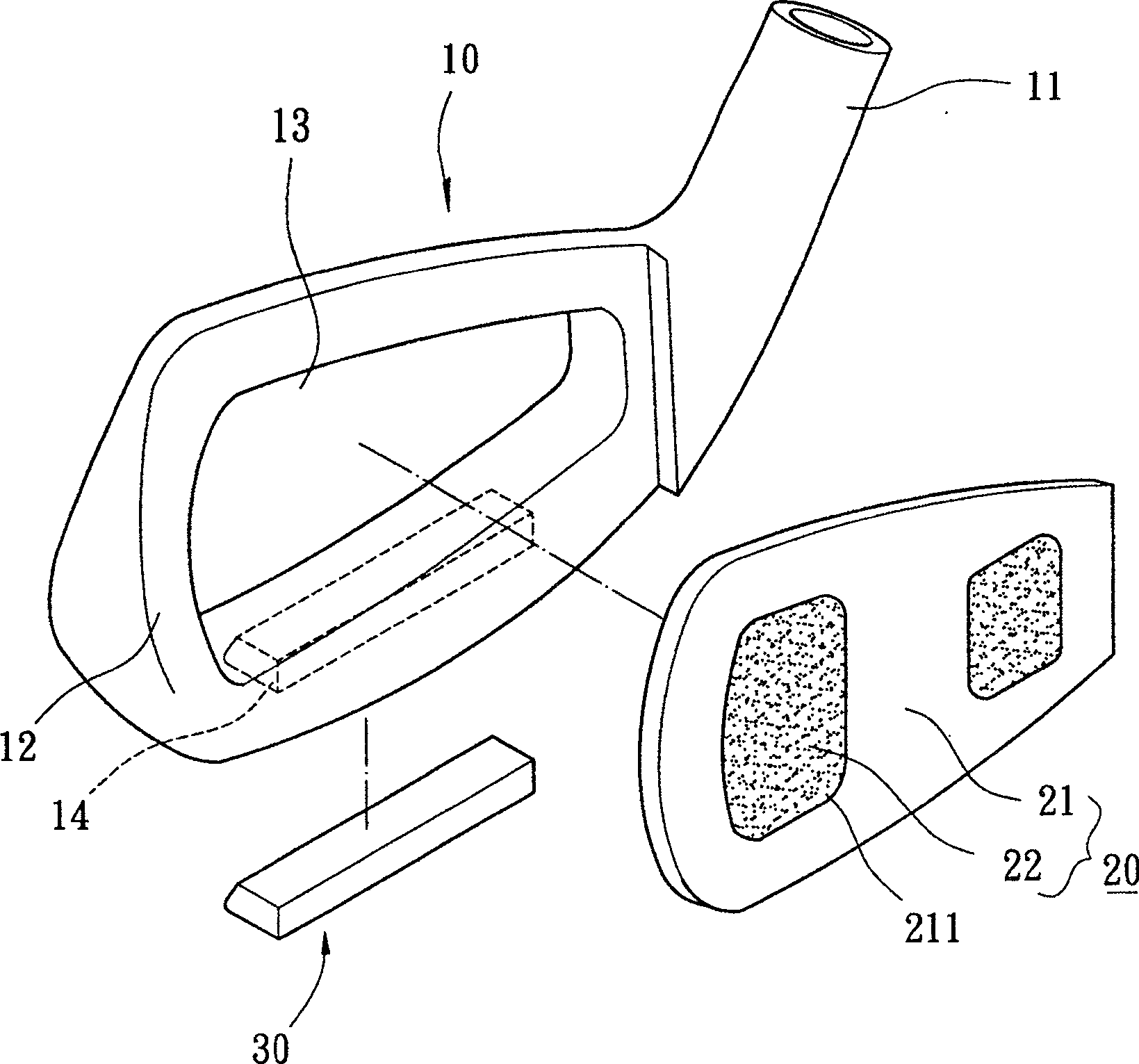
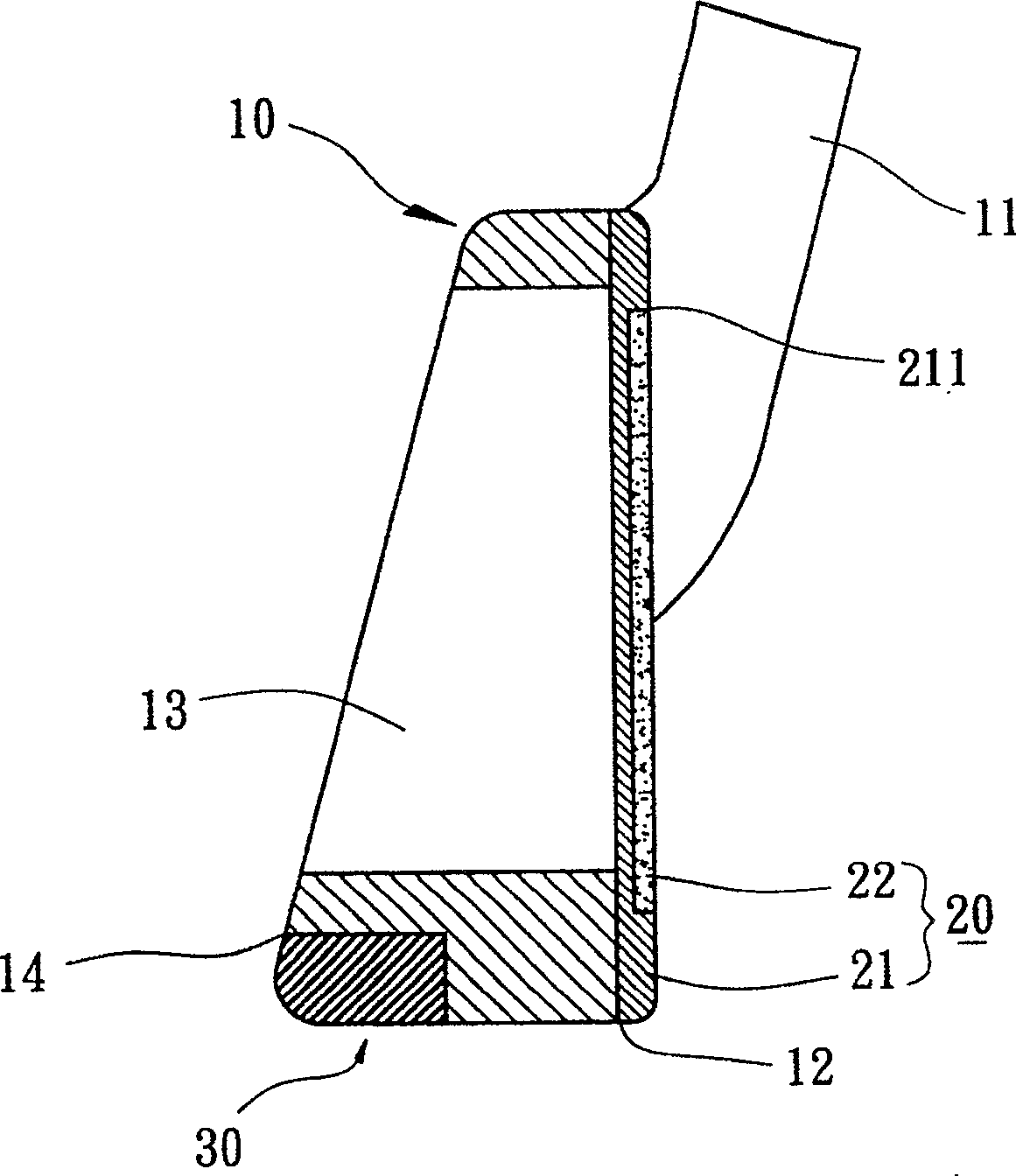
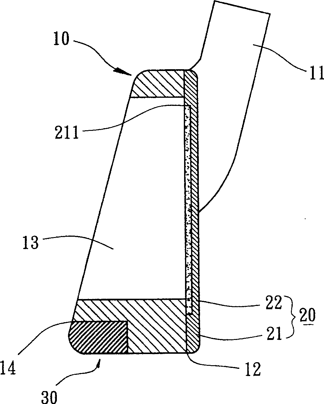
[0030] Please refer to figure 1 , 2 As shown, the structure of the golf club head with a low center of gravity in the first embodiment of the present invention essentially includes a body portion 10, a striking panel portion 20, and a counterweight portion 30, which together form a golf club head. The golf club head will be referred to below as Iron-type [iron] and wood-type [wood] club heads are taken as examples, but they can also be selected from conventional club heads such as utility or putter.

[0031] please refer again figure 1 , 2 As shown, the body portion 10 of the first embodiment of the present invention is an iron club head, which is preferably made of appropriate metal, alloy material or non-metallic material, suc...


PUM


Abstract

A golf rod tip structure with a low centre of gravity, comprising a body and a striking panel. A binding part is provided on the front of the body. A metal base material and at least a lightweight intensified material are provided on the striking panel. The metal base material makes up a basic construction of the striking panel, and has at least one recess to combine the lightweight intensified material. The weight of the striking panel is decreased base on the lightweight intensified material,and it is facilitated to adjust the position of the integral centre of gravity rearwards and downwards.

Description

technical field [0001] The present invention relates to a low-center-of-gravity golf club head structure, in particular to making a striking panel part by compounding a metal base material and at least one reinforcing material whose specific gravity is smaller than that of the metal base material, so as to reduce the weight of the hitting panel part. Furthermore, it is beneficial to adjust the golf club head structure of the whole center of gravity of the club head. Background technique [0002] Please refer to the US Patent No. 5,439,223 "Golf Club Head" for the structure of the existing golf club head, which includes a body part, a striking panel part and a counterweight part. The body part is further provided with a set of neck and an assembly port. The sleeve neck is respectively formed on one side of the main body in an integral molding or combined manner. The assembling port is substantially recessed at the bottom of the back of the main body for embedding and combin...

Claims


Application Information

Patent Timeline
Patent Type & Authority Patents(China)
IPC IPC(8): A63B53/04A63B60/02A63B102/32
Inventor 黄峻勇
Owner NELSON PRECISION CASTING
Why Eureka
Try Eureka