Projection system and method for forming color image

A projection system and color ribbon technology, applied in the field of projection systems, can solve problems such as difficulty in imaging signals

Inactive Publication Date: 2009-06-24
SAMSUNG ELECTRONICS CO LTD
View PDF4 Cites 0 Cited by
  • Summary
  • Abstract
  • Description
  • Claims
  • Application Information

AI Technical Summary

Problems solved by technology

However, it is difficult to continuously process changing imaging signals

Method used


Image

  • Projection system and method for forming color image
  • Projection system and method for forming color image
  • Projection system and method for forming color image

Examples


Embodiment Construction

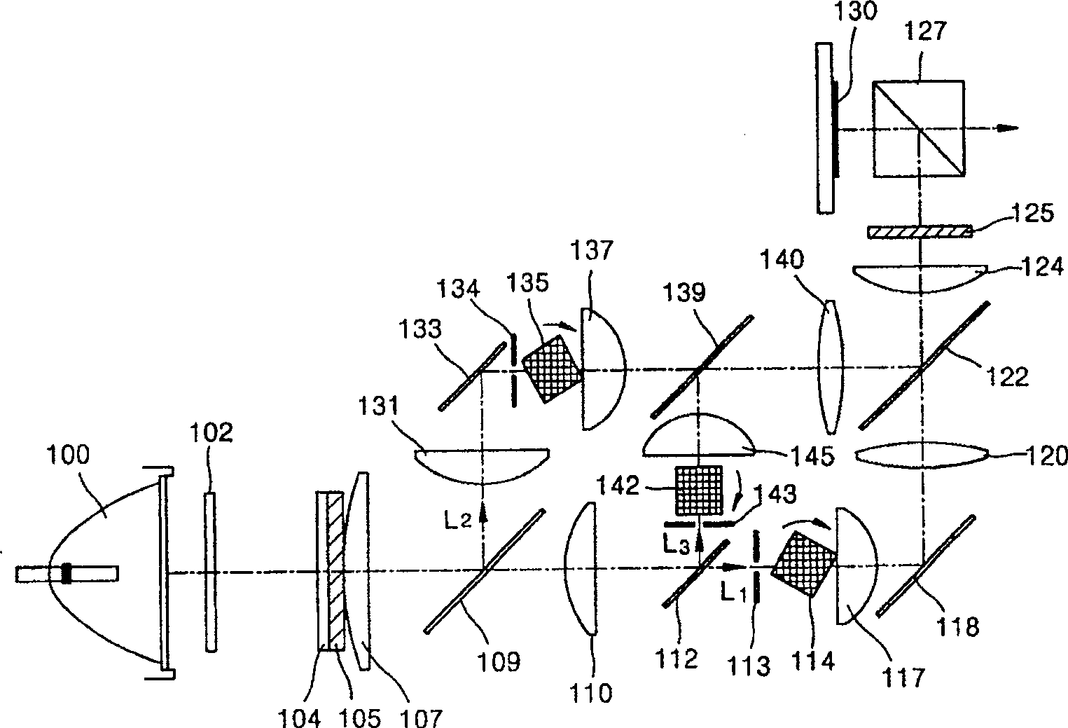
[0072] refer to Figure 4 , the projection system according to one embodiment of the present invention includes: a light source 50 , at least one filter, a scroll unit 20 , a color separator 55 , and a light valve 40 . At least one filter is installed on the focal plane of the light emitted from the light source 50, and has a slit for controlling the divergence angle of the incident light or the viewing angle (etendue) of the optical system. The rolling unit 20 makes incident light incident on the color separator 55 at different angles and scrolls the incident light. The color separator 55 separates light passing through the scroll unit 20 according to colors. The light valve 40 processes the color light beams generated by the color separator 55 according to the input imaging signal and forms a picture.

[0073] The picture formed by the light valve 40 is enlarged by the projection lens unit 45 , and then the enlarged picture is projected onto the display screen 48 .

[007...


PUM


Abstract

A projection system and method for forming color images are provided. In this method, the rise time and fall time of the imaging signal are changed required to obtain multiple color bands formed on the light valve. First, install at least one filter with slits. Next, the incident light is rolled by converting the rotation of the rolling unit into a linear motion of the incident light passing through the lens element of the rolling unit. The light beam emitted from the light source is then separated according to color using a color separator containing a plurality of color-selective mirrors, each of which transmits the incident beam as a beam of one wavelength and reflects a beam of another wavelength. Then, multiple color beams separated by the color separator and rolled by the rolling unit are incident on the corresponding color areas on the light valve, thereby generating multiple color strips. Then a black band is formed between adjacent color bands by controlling the distance between adjacent color selection mirrors or controlling the width of the slit.

Description

technical field [0001] The present application relates to a method for forming a color image using color scrolling technology and a projection system using the method, and more particularly to a method for forming a color image, which generates a black band between two color bands formed on a light valve, and controls the black band Ribbon Width Obtains the rise and fall times required to vary the imaging signal of the ribbon, and a projection system employing this method. Background technique [0002] According to the number of light valves, the projection system is divided into three-plate projection system and single-plate projection system. The light valve is used to control the on / off operation of the light emitted by the high-output light source on the pixel array substrate and form an image. A single-plate projection system has a smaller optical system than a three-plate projection system. However, because the single-panel projection system sequentially uses red (R),...

Claims


Application Information

Patent Timeline
Patent Type & Authority Patents(China)
IPC IPC(8): G02B27/00H04N9/31G02F1/13G02F1/1335G02F1/13357G03B21/14
CPCH04N9/3197H04N9/3117H04N9/3152
Inventor 赵虔皓金大式金成河李羲重
Owner SAMSUNG ELECTRONICS CO LTD
Why Eureka
Try Eureka