Eureka AIR delivers breakthrough ideas for toughest innovation challenges, trusted by R&D personnel around the world.

Power cord spooling machine

A technology of wire winder and power cord, which is applied in the direction of circuits, electrical components, devices with bendable lead wires, etc., and can solve problems such as looseness, disorder, and affecting indoor appearance

Inactive Publication Date: 2009-06-24
庞一鸣
View PDF8 Cites 0 Cited by
  • Summary
  • Abstract
  • Description
  • Claims
  • Application Information

AI Technical Summary

Problems solved by technology

[0002] At present, the power cords of household appliances are wrapped and hung on the back of the household appliances. After the user unwinds the wires for the first time, he drags the remaining wires behind the machine. With the increase of types of household appliances, the wires are spread out in disorder Hanging, it looks messy, which not only affects the appearance of the interior, but also adds trouble to the relocation
CN2708919Y proposes a wire winder that elastically restores the original shape through the crimping spring, so that the pulled out part can be rolled back into the box, and the length of the power cord can be controlled by this rewinding force, so as to change the dragging phenomenon of the power cord, but due to the crimping The rebound force of the spring is proportional to the pulled-out length, the longer the pull-out length, the greater the pull-back force, which makes the pull-out power cord plugged into the plug, and the spring-back force keeps the plug in tension all the time The pulling state affects the fastness and reliability of the joint between the plug and the socket
Furthermore, the longer the power cord, the greater the rebound force, and the greater the vibration and shaking force on the other end of the power cord during the rebound, which will easily make the electrical contacts of the electrical appliance itself loose due to vibration, thereby affecting the reliability of the electrical contacts.

Method used


Image

  • Power cord spooling machine
  • Power cord spooling machine

Examples


Embodiment Construction

[0010] The present invention will be further described below in conjunction with accompanying drawing.

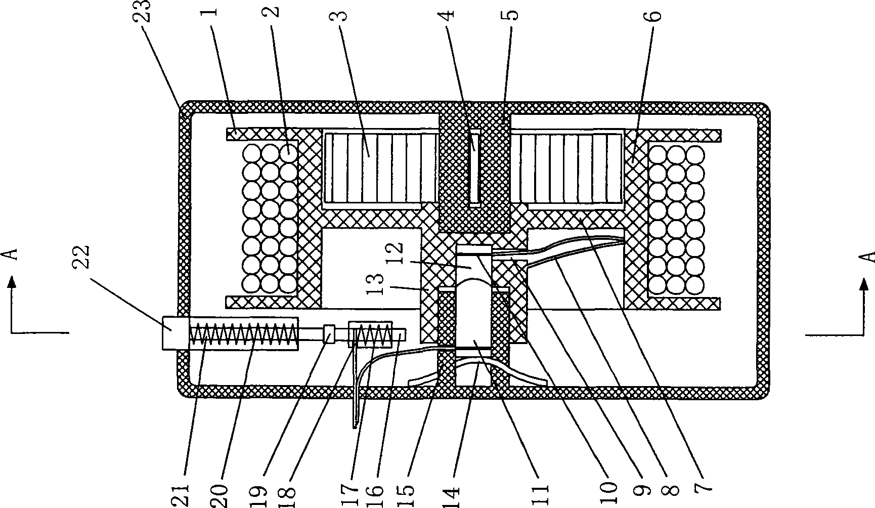
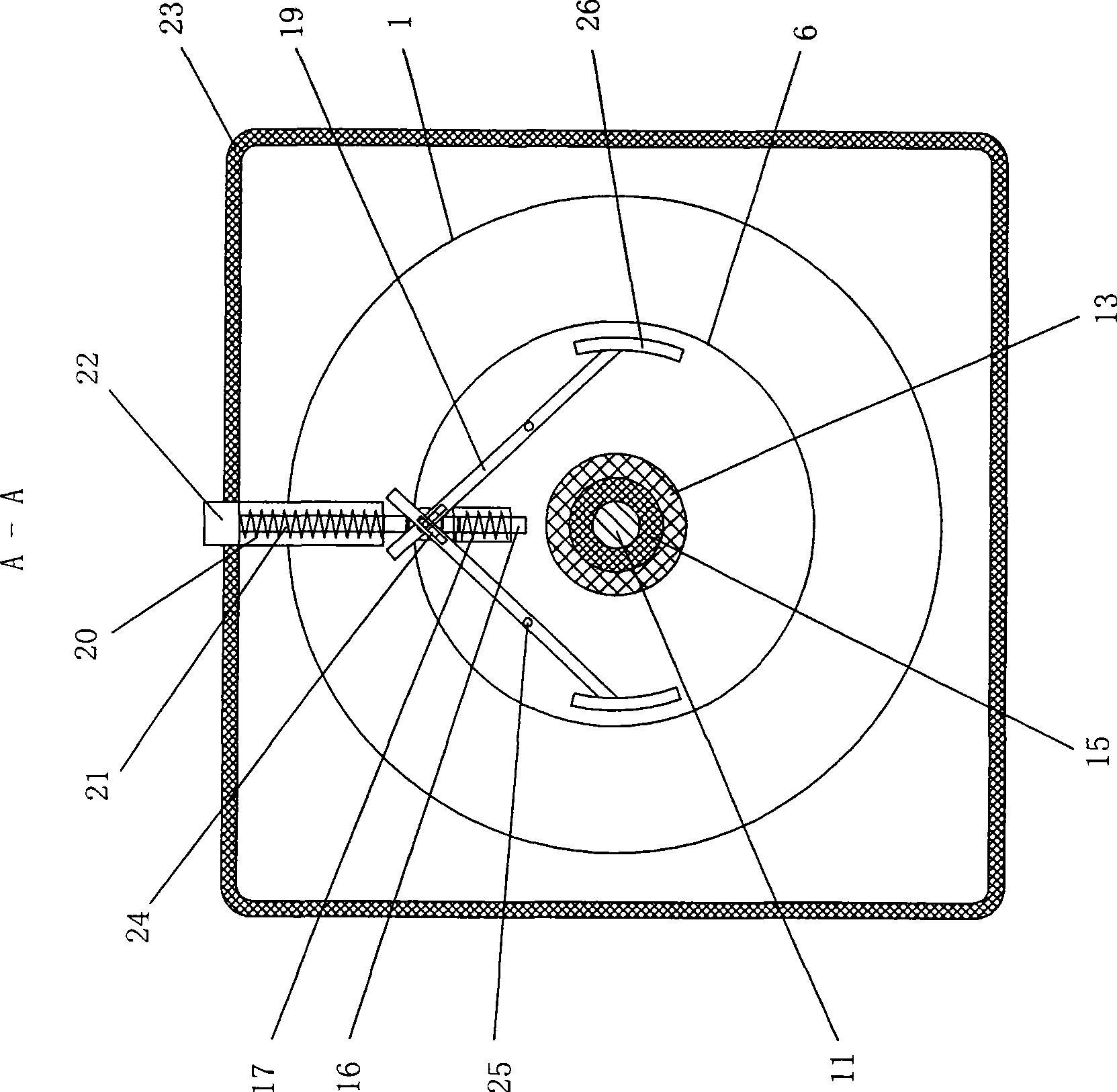
[0011] refer to figure 1 As shown, the winding box 23 includes a coil spring assembly, a coiled power cord assembly, an electrical connection assembly, and a stop engagement assembly. The crimping spring sheet 3 takes the bobbin core 5 as the center and is wound outside the bobbin core 5 in a concentric winding manner. Shrink shrapnel socket 4 is fixed, and the other end is fixed on the base of reel 6. When pulling the power cord 2 wound on the reel 6, the reel 6 rotates to drive one end of the shrink spring fixed on the base of the reel 6 to rotate, so that the reel spring is fixed with its fixed bobbin core. 5 is rotated as the center and gradually tightened to generate a crimping force. When the power cord 2 is released, the biased crimping spring 3 restores its original shape and drives the reel 6 to move in the opposite direction. This rotational movement is the same...


PUM


Abstract

A power cord winder, which includes a winding box, a winding wheel located in the winding box and wire limiting rings at both ends, a coil spring connected to the winding shaft core at one end inside the winding sleeve, and is characterized in that An electrical connection assembly consisting of a conductive outer layer, an insulating inner layer and a conductive shaft core is provided on the protruding part of the bobbin sleeve; the outer side of the wire limiting ring is provided with a stopping rod connected to a vertical terminal to prevent the reel from rotating. Detent engagement assembly that simultaneously engages a set of electrical contacts. The synchronous interlocking function of the stopper and the electrical connection of the present invention can reduce the tension of the plug and the power cord so that the plug and the socket can be joined firmly, and there is no electricity when winding the wire, which increases the safety of household appliances and can effectively prevent random winding or breaking in the box. Knot.

Description

technical field [0001] The invention relates to a wire winding device, in particular to a wire take-up box for power cords of household appliances. Background technique [0002] At present, the power cords of household appliances are wrapped and hung on the back of the household appliances. After the user unwinds the wires for the first time, he drags the remaining wires behind the machine. With the increase of types of household appliances, the wires are spread out in disorder Hanging, it looks messy, which not only affects the appearance of the interior, but also adds trouble to the relocation. CN2708919Y proposes a wire winder that elastically restores the original shape through the crimping spring, so that the pulled out part can be rolled back into the box, and the length of the power cord can be controlled by this rewinding force, so as to change the dragging phenomenon of the power cord, but due to the crimping The rebound force of the spring is proportional to the p...

Claims


Application Information

Patent Timeline
Patent Type & Authority Patents(China)
IPC IPC(8): H01R13/72H01R13/70B65H75/34
Inventor 庞一鸣
Owner 庞一鸣
Why Eureka
Eureka Blog
Learn More