
Leaded light lens and luminous diode packaging structure having same

A technology of light-emitting diodes and packaging structures, which is applied to lenses, optics, optical components, etc., can solve the problems of high cost, complicated assembly, and large loss of light energy, and achieve the effects of reducing manufacturing costs, saving the number of mold cores, and having a simple structure.

Inactive Publication Date: 2009-07-01
IND TECH RES INST
View PDF9 Cites 0 Cited by
  • Summary
  • Abstract
  • Description
  • Claims
  • Application Information

AI Technical Summary

Problems solved by technology

[0005] The saw-toothed structure of the outer surface 11 is designed according to the calculation of light rays at various angles of the light-emitting diode, so that the light can be emitted from the side. However, the outer surface of the saw-toothed structure can only guide the light to a general trend, and cannot guide each A light guide at an angle is emitted from the side, especially the light emitted to the top of the light-emitting diode, it is inevitable that there will still be a bright spot, so in practical applications, a transparent plate must be installed above the lens cover 1, and then the transparent plate Paste a reflective sheet on the top to cover the bright spot, thus resulting in complicated and high cost of assembly
[0006] The light is emitted from the side by one refraction or one total reflection and then refraction again. However, when the light is refracted from an optically dense medium into an optically sparse medium, the larger the incident angle, the greater the loss of light energy. The light from the light emitting diode 2 passes through The light energy lost after the light is refracted by the lens cover 1 will affect the brightness of subsequent applications such as liquid crystal displays
[0007] Furthermore, the sawtooth structure of the outer surface 11 of the lens cover 1 is very complicated and must be made by combining multiple sets of mold cores, thus increasing the product cost

Method used


Image

  • Leaded light lens and luminous diode packaging structure having same
  • Leaded light lens and luminous diode packaging structure having same
  • Leaded light lens and luminous diode packaging structure having same

Examples


Embodiment

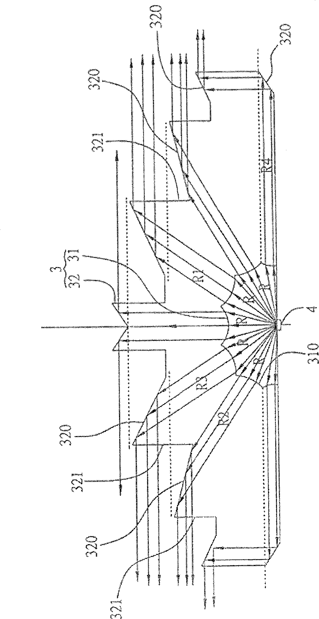
[0027] see figure 2 , which is a schematic diagram of the light guide lens of the present invention, the light guide lens of the present invention is used to modulate the incident light R in each direction and emits toward the side, the light guide lens 3 includes: a lens with a light incident surface 31 and a light exit surface 32 The main body 3 is made of resin or polymer transparent material, etc.; multiple refraction structures 310 arranged on the light-incident surface 31 are used to refract light R to turn to the light-exit surface 32, and a single refraction structure 310 makes incident light rays of different angles R parallel refraction; and a plurality of reflective structures 320 arranged on the light exit surface 32, used to reflect the light from each corresponding part of the refraction structure 310 to the side light exit of the lens body 3, and parallel refraction from the single refraction structure 310 All the light rays correspond to the single reflective ...


PUM


Abstract

The invention discloses a light guide lens, which is used for modulating incident light from various directions to emit light toward the side. The light guide lens comprises: a lens body having a light incident surface and a light exit surface; a plurality of refraction structures, and the refraction structures are connected to each other and spread on the light incident surface, and are used to refract light rays of various angles toward the light exit surface, and a single refraction structure makes the incident light rays of different angles refract in parallel; The multiple reflective structures on the light exit surface are used to reflect the light from each corresponding part of the refraction structure to the side light exit of the lens body, and the parallel refracted light rays from a single refraction structure all correspond to the single reflective structure, so that the incident light Light is emitted toward the side. In addition, the present invention also provides a light-emitting diode packaging structure with the light-guiding lens. The light guide lens and the light emitting diode packaging structure with the light guide lens of the present invention can modulate the incident light into side light, simplify the assembly process, reduce the manufacturing cost, and make full use of light energy.

Description

technical field [0001] The present invention relates to a light-guiding lens and a light-emitting diode packaging structure, in particular to a light-guiding lens for modulating incident light from various directions of a light-emitting diode light source to emit toward the side and a light-emitting diode packaging structure having the light-guiding lens . Background technique [0002] Backlight modules of traditional liquid crystal displays mostly use cold-cathode fluorescent tubes (CCFL) as light sources. However, due to the mercury content of cold-cathode fluorescent tubes, and the disadvantages of high power consumption and short life, the current trend is to use light-emitting diodes ( Hereinafter referred to as LED) to replace the cold cathode fluorescent tube as the light source of the backlight module. LEDs have the characteristics of long life and no pollution problems. If red, green, and blue monochromatic LED light sources are used, they have the advantages of si...

Claims


Application Information

Patent Timeline
Patent Type & Authority Patents(China)
IPC IPC(8): G02B3/08G02B17/00H01L33/00
Inventor 鲍友南姚柏宏林宗信
Owner IND TECH RES INST
Learn More