
Fixing structure of optical film

A technology of fixed structure and optical film, applied in optics, nonlinear optics, instruments, etc., can solve the problems of insufficient strength, falling, and large relative movement of the film, so as to reduce the warping effect.

Inactive Publication Date: 2009-07-08
CPT TECH GRP
View PDF5 Cites 1 Cited by
  • Summary
  • Abstract
  • Description
  • Claims
  • Application Information

AI Technical Summary

Problems solved by technology

However, due to the thin thickness and insufficient strength of the membrane material, in the environment of thermal expansion and cold contraction, the longitudinal and transverse expansion of different membrane materials will make the membrane material prone to warping
[0007] In addition, when the traditional optical film fixing method uses fixed holes to fix the film, only long holes horizontal to the module are provided
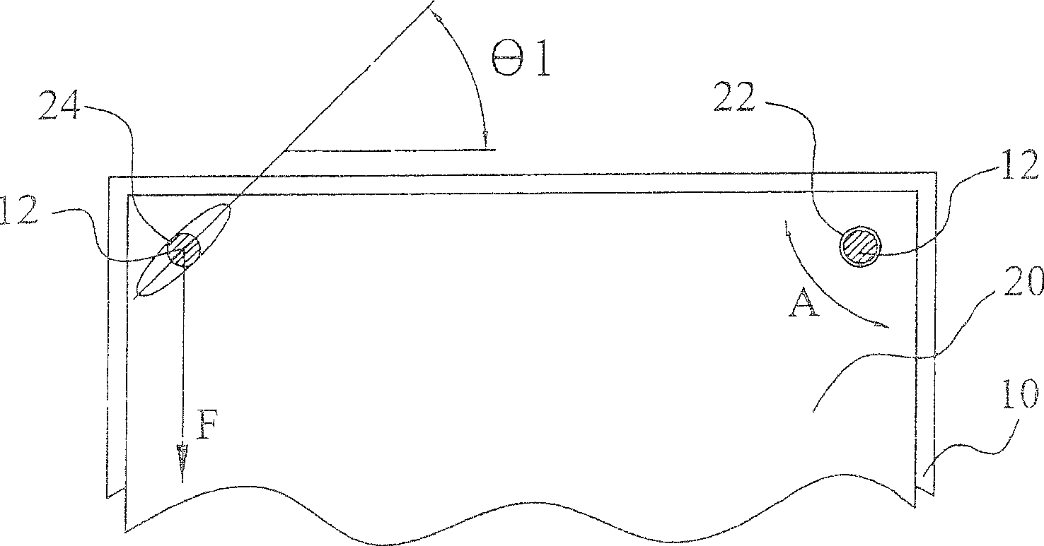
If this method encounters heat expansion and contraction, the friction force will be increased due to the influence of the gravity of the membrane material, making it difficult for the pores of the membrane material to absorb the expansion in the horizontal direction, and the relative movement of the membrane material during vibration is large, which may easily lead to warping and The problem of tiny particles falling occurs, once the phenomenon of electrostatic adsorption occurs, it cannot be ruled out, resulting in a serious decline in optical quality

Method used


Image

  • Fixing structure of optical film
  • Fixing structure of optical film
  • Fixing structure of optical film

Examples


Embodiment Construction

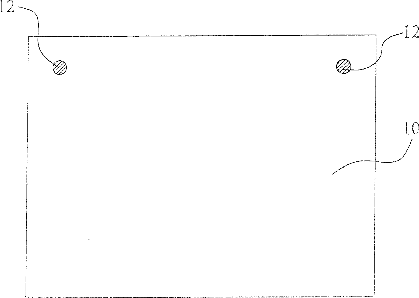
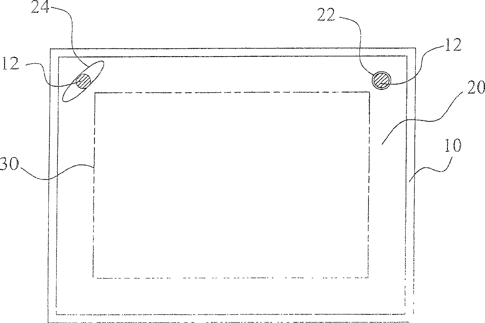
[0035] Figure 1A and Figure 1B Shown is a schematic front view of an embodiment of the fixing structure of the optical film according to the present invention. In this embodiment, if Figure 1A As shown, a bottom plate 10, the bottom plate 10 can be the back plate of the backlight module, the back frame, the side frame or other supporting plates that can carry the flat film. On the bottom plate 10, two fixing elements 12, such as fixing pins, are disposed thereon. see next Figure 1B , a first film material 20 is placed on the bottom plate 10 , and a first fixing hole 22 and a second fixing hole 24 are disposed on the first film material 20 . Wherein, the first fixing hole 22 and the second fixing hole 24 are respectively arranged at the horizontal position on the upper side of the first film material 20, and the fixing elements 12 on the bottom plate 10 pass through the first fixing hole 22 and the second fixing hole respectively. 24 , wherein the first fixing hole 22 is...


PUM

PropertyMeasurementUnit
thicknessaaaaaaaaaa

Abstract

The invention relates to a fixing structure for an optic diaphragm, which comprises a base board, a plurality of fixing elements on the base board, and a first diaphragm material on the base board. Wherein, the first diaphragm material has a first fixing hole and a second fixing hole that are located at the horizontal location on the upper side of the first diaphragm material and the second fixing hole is of a first angle with the horizontal direction, and the fixing elements respectively pass the first fixing hole and the second fixing hole correspondingly. By arranging fixing holes of the diaphragm materials and reserving holes for the moving position, the invention makes all diaphragm materials of different thermal expansion coefficients to move toward a preset direction, which eliminates any movement interference between diaphragm materials.

Description

technical field [0001] The invention relates to an optical film material of a backlight module, in particular to a fixing structure of an optical film. Background technique [0002] In view of the rapid development of thin-film transistor manufacturing technology, liquid crystal displays have been widely used in electronic product display devices, such as personal Consumer electronics or computer products such as digital assistants, portable TVs, mobile phones, camcorders, notebook computers, and desktop displays, but because LCDs are non-luminous display devices, they need backlight modules to produce displayed function. [0003] The backlight module includes a light guide plate, a reflection plate, a light source, an optical film material composed of several layers of thin films and an aluminum back plate. The optical film is composed of several layers of films and is arranged on the upper surface of the light guide plate. These films include a lower diffuser, a prism, a...

Claims


Application Information

Patent Timeline
Patent Type & Authority Patents(China)
IPC IPC(8): G02F1/1333
Inventor 林义文陈知坚李宜锡
Owner CPT TECH GRP
Learn More