Heat exchanger
A technology of heat exchangers and heat transfer tubes, applied in heat exchange equipment, lighting and heating equipment, evaporators/condensers, etc., can solve the problems of increased gas ventilation resistance and not easy to flow down, and achieve the purpose of suppressing ventilation resistance Effect
- Summary
- Abstract
- Description
- Claims
- Application Information
AI Technical Summary
Problems solved by technology
Method used
Image
Examples
Embodiment 1
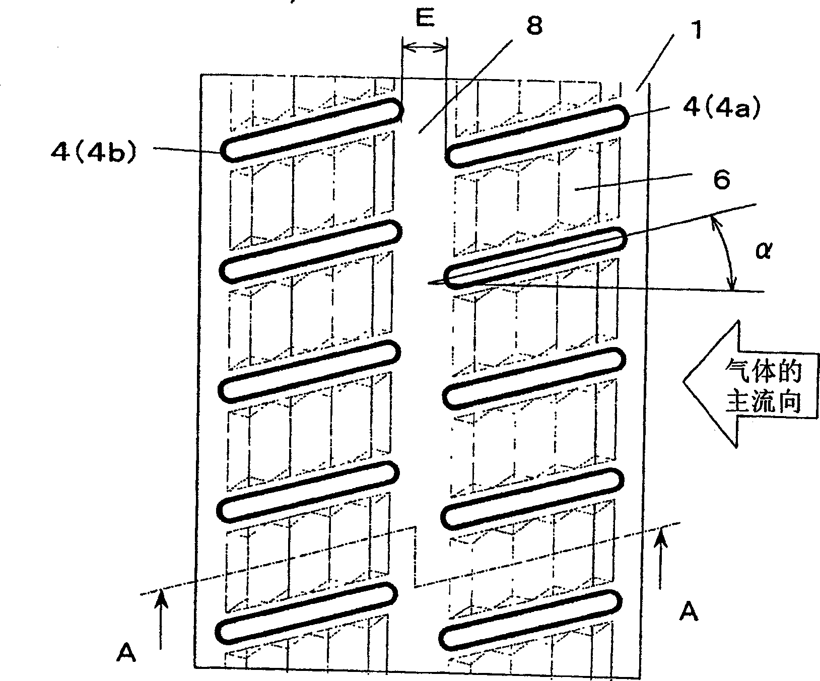
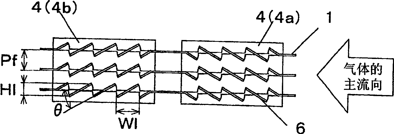
[0036] figure 1 It is a front view of the fin 1 in which the flat heat transfer tube 4 is inserted in the heat exchanger according to the first embodiment of the present invention. figure 2 for along figure 1 The cross-sectional view in the direction of arrow A—A, figure 2 is a schematic diagram of a stacked state of a plurality of fins 1 inserted with flat heat transfer tubes 4 in the heat exchanger according to Example 1 of the present invention.
[0037] exist figure 1 , figure 2 Among them, when the heat exchanger is used as an evaporator, the main direction of the gas, that is, the "column direction" is set in the horizontal direction, and the direction perpendicular to the main direction of the gas, that is, the "layer direction" is set in the vertical direction .
[0038] The heat transfer tubes 4 with flat outer edges of the cross-section are inserted into the fins 1 roughly vertically with a specified column spacing and layer spacing. The flat heat transfe...
Embodiment 2
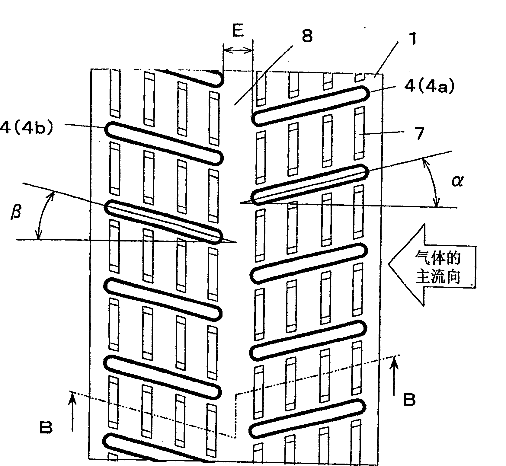
[0050] image 3 It is a front view of the fin 1 inserted with the flat heat transfer tube 4 in the heat exchanger of Example 2 of the present invention, Figure 4 for along image 3 A cross-sectional view in the direction of arrow BB of , which shows a schematic diagram of multi-layered fins 1 inserted with flat heat transfer tubes 4 in the heat exchanger according to Embodiment 2 of the present invention.
[0051] Such as image 3 , Figure 4 As shown in , the heat transfer tube 4 with a flat outer edge of the cross-section is inserted into the fin 1 approximately vertically to form a double-row and multi-layer structure with a specified row spacing and layer spacing, and the adjacent double rows The heat transfer tubes 4 are staggered from each other. In addition, the flat heat transfer tubes 4a in the upwind row form a slope that descends on the leeward side with an inclination angle α of about 5° to 30° relative to the main flow direction of the gas, while the flat hea...
Embodiment 3
[0063] Figure 5 It is a front view of the fin 1 inserted with the flat heat transfer tube 4 in the heat exchanger of Example 3 of the present invention, Figure 6 for along Figure 5 The view seen by the arrows C—C in the figure shows a schematic diagram of the fin 1 inserted with the flat heat transfer tube 4 in the heat exchanger of Embodiment 3 of the present invention.
[0064] exist Figure 5 , Figure 6 , the heat transfer tubes 4 with a flat outer edge of the cross-section are inserted into the fins 1 approximately vertically to form a double-row multi-layer structure with a specified column spacing and layer spacing, and the adjacent heat transfer tubes in the double row 4 are staggered from each other. And, the flat heat transfer tubes 4a of the windward row are inserted through the notch 3a on the windward leading edge of the fin 1, and the flat heat transfer tubes 4b of the leeward row are inserted through the notch 3b on the leeward trailing edge of the fin 1....
PUM
| Property | Measurement | Unit |
|---|---|---|
| Height | aaaaa | aaaaa |
Abstract
Description
Claims
Application Information
 - R&D
- Intellectual Property
- Life Sciences
- Materials
- Tech Scout
- Unparalleled Data Quality
- Higher Quality Content
- 60% Fewer Hallucinations
Browse by: Latest US Patents, China's latest patents, Technical Efficacy Thesaurus, Application Domain, Technology Topic, Popular Technical Reports.
© 2025 PatSnap. All rights reserved.Legal|Privacy policy|Modern Slavery Act Transparency Statement|Sitemap|About US| Contact US: help@patsnap.com


