
Finned tube heat exchanger and refrigeration cycle device equipped with it

A heat exchanger and finned tube technology, applied in the field of refrigeration cycle devices, can solve the problems of damaged heat exchange efficiency, damaged heating capacity, and increased thermal resistance, so as to suppress the increase of ventilation resistance and prevent unsatisfactory Uniform frosting and improved thermal conductivity

Active Publication Date: 2018-06-12
MITSUBISHI ELECTRIC CORP
View PDF7 Cites 0 Cited by
  • Summary
  • Abstract
  • Description
  • Claims
  • Application Information

AI Technical Summary

Problems solved by technology

Therefore, there is a problem that an increase in thermal resistance between the gas flowing on the surface of the flat tube and the fluid inside the flat tube, and an increase in ventilation resistance occur, resulting in a significant impairment of heat exchange efficiency.
In addition, when the discharge of condensed water is promoted by using the cutout opening on the windward side with respect to the airflow as a water guide path, frost will form unevenly on the cutout due to the leading edge effect of the temperature boundary layer.
Therefore, there is a problem that the heating capacity is impaired due to an increase in ventilation resistance

Method used


Image

  • Finned tube heat exchanger and refrigeration cycle device equipped with it
  • Finned tube heat exchanger and refrigeration cycle device equipped with it
  • Finned tube heat exchanger and refrigeration cycle device equipped with it

Examples


Embodiment approach 1

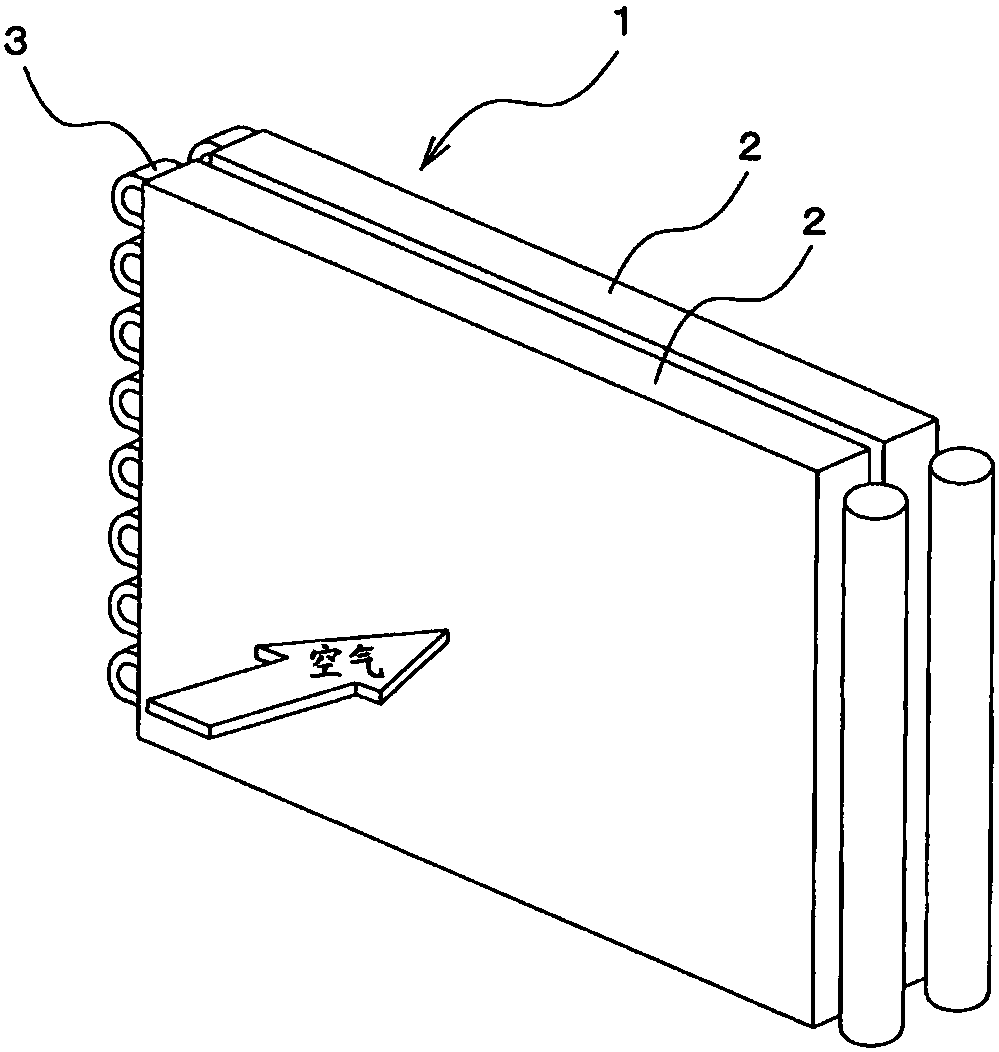
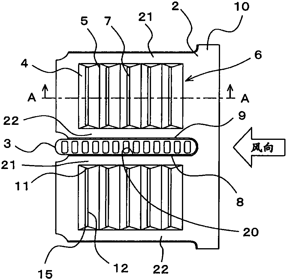
[0026] figure 1 It is a perspective view of the fin-tube heat exchanger according to Embodiment 1 of the present invention. figure 2 is showing figure 1 A plan view of the flat tube penetration portion of the plate fin used in the finned tube heat exchanger. image 3 yes figure 2 A-A line to see the cross-sectional view.

[0027] Such as Figure 1 ~ Figure 3 As shown, the finned tube heat exchanger (hereinafter, simply referred to as "heat exchanger") 1 according to the first embodiment has a plurality of rectangular plate-shaped fins 2 arranged in parallel, and gas flows between them. and a heat transfer tube (hereinafter referred to as "flat tube") 3 with a flat cross-sectional shape, which is inserted into the cutout portion 20 of the above-mentioned plate-shaped fin 2 at right angles and along the length of the plate-shaped fin 2 Multiple layers are provided in the side direction (=layer direction), and the working fluid passes through the inside of the heat transfe...

Embodiment approach 2

[0044] Figure 4 It is a perspective view showing the flat tube penetration portion of the plate-shaped fin used in the fin-tube heat exchanger according to Embodiment 2 of the present invention. Figure 5 It is a plan view showing the flat tube penetration portion of the plate-shaped fin used in the fin-tube heat exchanger according to Embodiment 2 of the present invention. Figure 6 is shown from Figure 4 A side view of the flat tube penetration portion of the plate-shaped fin viewed from the direction of line BB in . In addition, the same code|symbol is attached|subjected to the part corresponding to Embodiment 1 mentioned above in each figure. In addition, refer to the aforementioned figure 1 .

[0045] Such as Figure 4 ~ Figure 6 As shown, in the heat exchanger 1 which is a finned tube heat exchanger according to Embodiment 2 of the present invention, in order to secure the gap between adjacent plate-shaped fins 2 , that is, the fin pitch (FP) , the plate-shaped ...


PUM


Abstract

The present invention relates to a fin-tube heat exchanger and a refrigeration cycle device including the fin-tube heat exchanger. The fin-tube heat exchanger includes: rectangular plate fins (2), which are stacked at intervals; and flat tubes (3), which are inserted at right angles to the stacked plate fins (2). Plate-shaped fins, and multiple layers are provided along the longitudinal direction of the plate-shaped fins (2), and heat conduction promotion parts are provided on the plate-shaped fins (2) and in the area between adjacent flat tubes (3) (6), the protrusions (4) and the depressions (5) whose ridgelines extend along the longitudinal direction of the plate fin (2) are alternately arranged to form the heat conduction promotion part (6), and the heat conduction promotion part ( 6) A cutout (7) connecting the front and back of the plate fin (2) is formed on the leeward side of the protruding portion (4).

Description

technical field [0001] The present invention relates to a finned tube heat exchanger using flat tubes, particularly a finned tube heat exchanger capable of improving dew condensation water discharge without impairing frost resistance, and a finned tube heat exchanger equipped with the same The refrigeration cycle device of the device. Background technique [0002] A conventional finned tube heat exchanger of this type uses a heat transfer tube whose cross-sectional shape is flat, that is, a flat tube, and has a heat conduction promotion part formed by alternately arranging protrusions and depressions on the surface of the plate fin. , thereby promoting heat conduction (for example, refer to Patent Document 1). [0003] In addition, there is also a structure in which the heat conduction promotion part on the surface of the plate-shaped fin is equipped with a cutout opening on the windward side with respect to the air flow, thereby promoting the discharge of condensed water g...

Claims


Application Information

Patent Timeline
Patent Type & Authority Patents(China)
IPC IPC(8): F25B39/00F25B41/00F28F1/12F28F17/00F25B41/40
CPCF25B39/00F28F1/124F28F17/005F25B41/40F25B39/02F28F1/32F28D1/05383F28F2215/10F28F2215/12F28F2215/08F28F1/325
Inventor 丹田翼石桥晃中村伸上山智嗣河岛绫
Owner MITSUBISHI ELECTRIC CORP
Learn More