
Air conditioner

A technology for air conditioners and ventilation ducts, which is applied in air conditioning systems, space heating and ventilation, household refrigeration devices, etc. The effect of compression

Active Publication Date: 2013-10-23
SHARP KK
View PDF4 Cites 0 Cited by
  • Summary
  • Abstract
  • Description
  • Claims
  • Application Information

AI Technical Summary

Problems solved by technology

[0009] However, since the protrusions listed in Patent Document 1 all have angular protruding corners on the side of the air passage, the air flowing through the air passage hits the protruding corners to generate turbulent flow, so the air flow cannot be completely eliminated. Unstable, thus hindering muting

Method used


Image

  • Air conditioner
  • Air conditioner
  • Air conditioner

Examples


Embodiment Construction

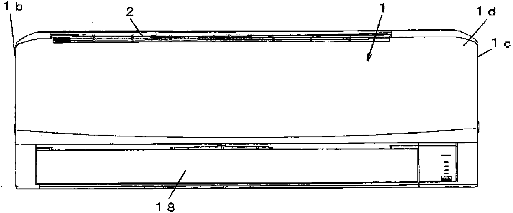
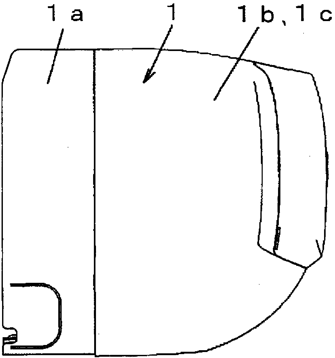
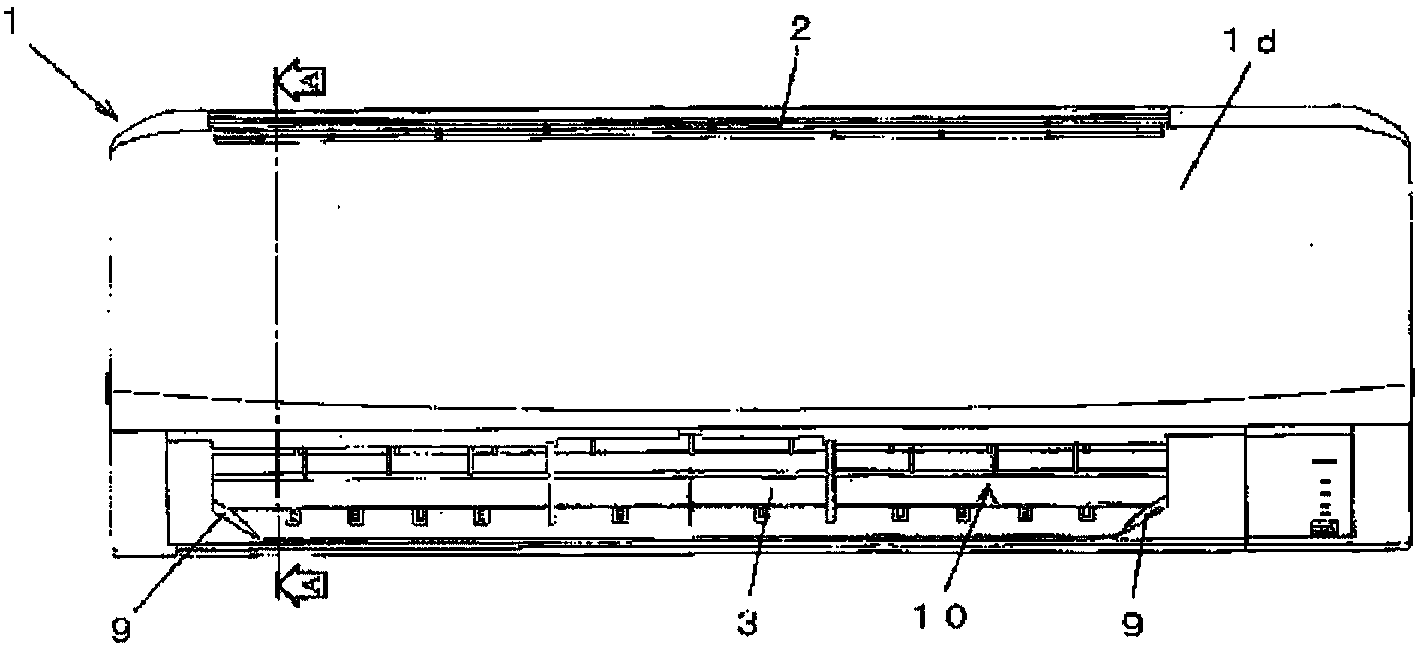
[0048] Hereinafter, embodiments of the present invention will be described based on the drawings. In this embodiment, an indoor unit of a separate air conditioner will be described as an example. This kind of air conditioner connects the heat exchanger housed inside the indoor unit and the compressor housed in the outdoor unit (not shown), the four-way valve, the outdoor heat exchanger, and the retracting device (not shown) through refrigerant pipes to form a cooling system. The circulation system can perform various operation modes such as cooling, heating, and dehumidification.

[0049] like Figure 5 As shown, the indoor unit has in the box 1: an air passage 4 from the suction port 2 to the air outlet 3; a heat exchanger 5 arranged on the upstream side of the air passage 4; a cross-flow fan 6 arranged in the air passage 4, the downstream side of the heat exchanger 5; and the cylindrical air passage wall 7 from the area downstream of the cross flow fan 6 to the blower port...


PUM


Abstract

The present invention is to provide an air conditioner provided with a cross flow fan having sufficient air blowing efficiency. The air conditioner includes, in a housing, an air passage extending from a suction port to a blowout port, a heat exchanger arranged at the upstream side of the air passage, a cross flow fan arranged in the air passage on the downstream side of the heat exchanger, and an air passage wall provided in a downstream area of the cross flow fan to reach the blowout port. A restricting section, which restricts an air passage sectional area, is provided at a corner section of the side wall of the air passage wall, which side wall is located at each of both shaft direction ends of the cross flow fan. The restricting section is formed to have a shape by which, in a downstream area of the cross flow fan, the air passage sectional area having a rectangular cross section expanding from the upstream side to the downstream side is restricted so as to reduce an enlargement ratio of the air passage sectional area. Further, the restricting section has a smooth restricting surface crossing the corner section of the cross section of the air passage, and the cross-sectional shape of the restricting surface is set to be gradually enlarged from the upstream side to the downstream side of the air flow.

Description

technical field [0001] The present invention relates to an air conditioner with a cross-flow fan. Background technique [0002] According to the recent trend of energy saving, high performance is required also in the air blower of the air conditioner. Higher performance of the blower refers to improving the flow rate characteristics of the air duct in which the blower is installed and making it less noisy. [0003] In order to respond to the above-mentioned needs, in conventional air conditioners, the high performance of the air blower has been achieved by enlarging the suction port of the air duct or by enlarging the shortest distance between the stabilizer and the rear guide arranged at the front and back of the cross flow fan constituting the air blower. change. [0004] However, this high-performance method improves the performance of the blower, but makes the blower a low-static pressure blower. Therefore, in actual use, when a large amount of dust adheres to the air...

Claims


Application Information

Patent Timeline
Patent Type & Authority Applications(China)
IPC IPC(8): F24F1/00
CPCF24F2001/0048F24F13/24F25D17/08F24F1/0011F24F1/0057
Inventor 高桥雅也大塚雅生白市幸茂
Owner SHARP KK
Learn More