Wind direction adjusting apparatus and indoor unit of air conditioner

A technology to adjust the device and wind direction, which is applied in the field of indoor units and can solve problems such as increased ventilation resistance and energy loss

Inactive Publication Date: 2013-06-19
MITSUBISHI ELECTRIC CORP
View PDF5 Cites 0 Cited by
  • Summary
  • Abstract
  • Description
  • Claims
  • Application Information

AI Technical Summary

Problems solved by technology

Therefore, the air flow collides with both the windward end surface of the first row of louvers and the windward end surface of the second row of louvers, increasing the ventilation resistance and causing energy loss.

Method used


Image

  • Wind direction adjusting apparatus and indoor unit of air conditioner
  • Wind direction adjusting apparatus and indoor unit of air conditioner
  • Wind direction adjusting apparatus and indoor unit of air conditioner

Examples


Embodiment approach 1

[0027] (Indoor unit of air conditioner)

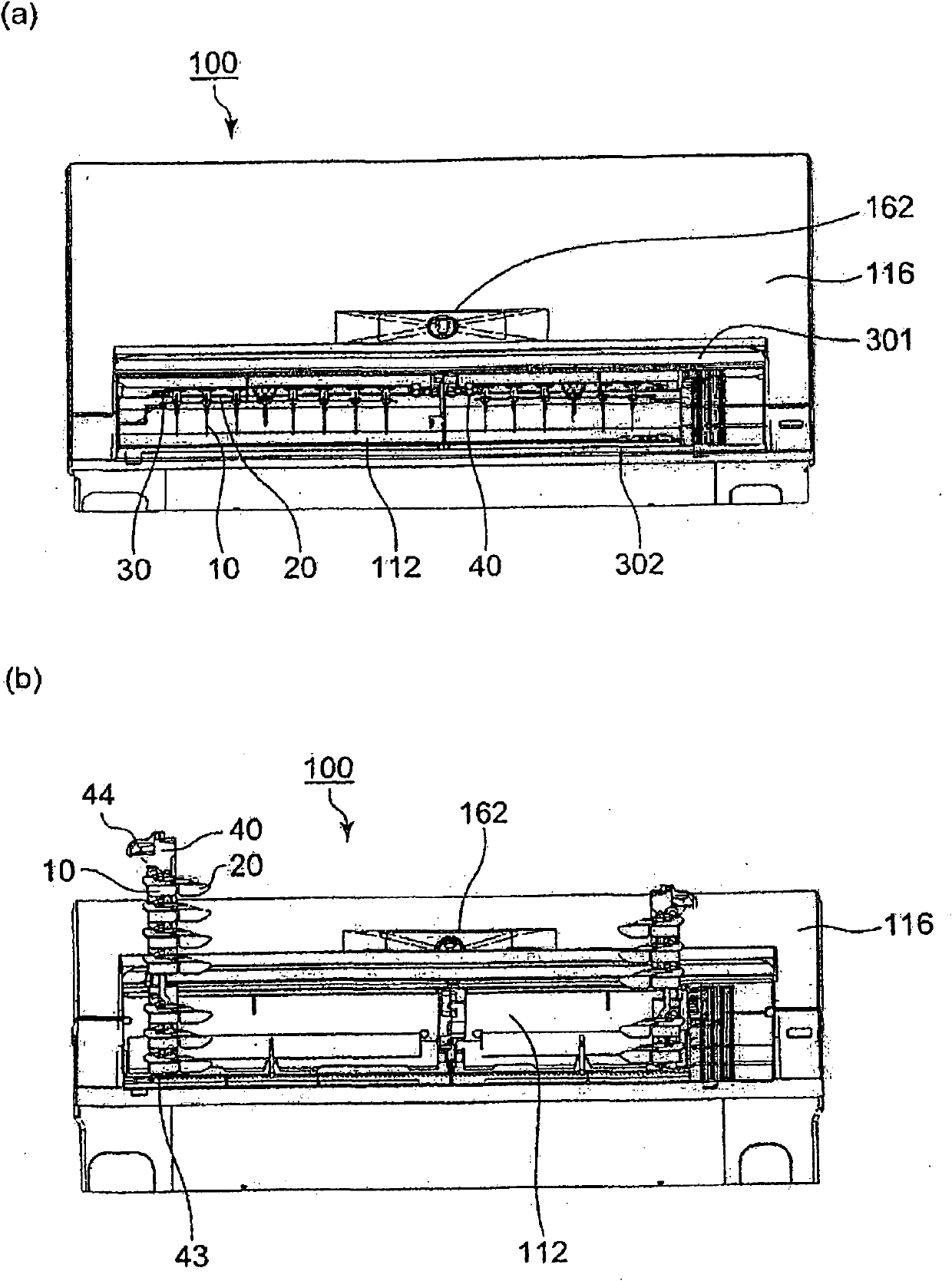
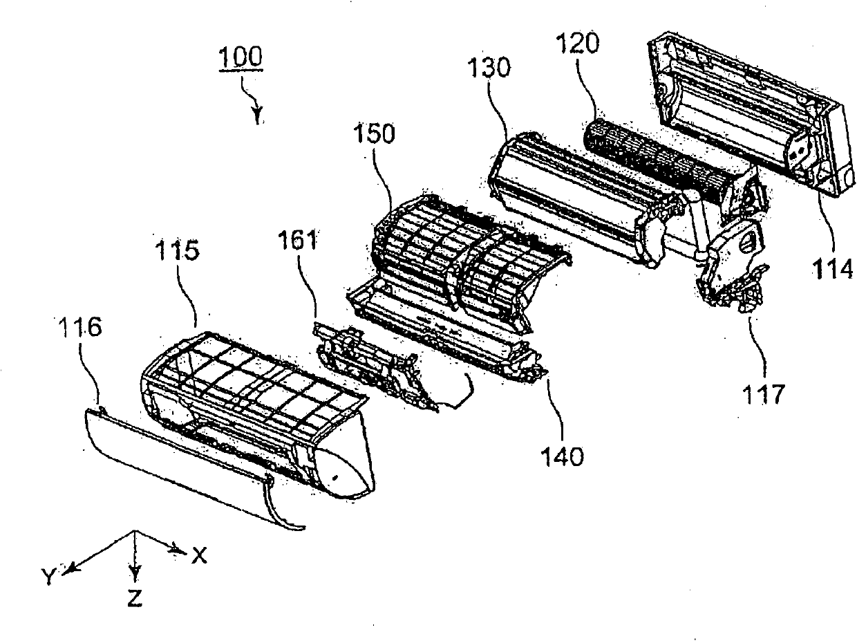
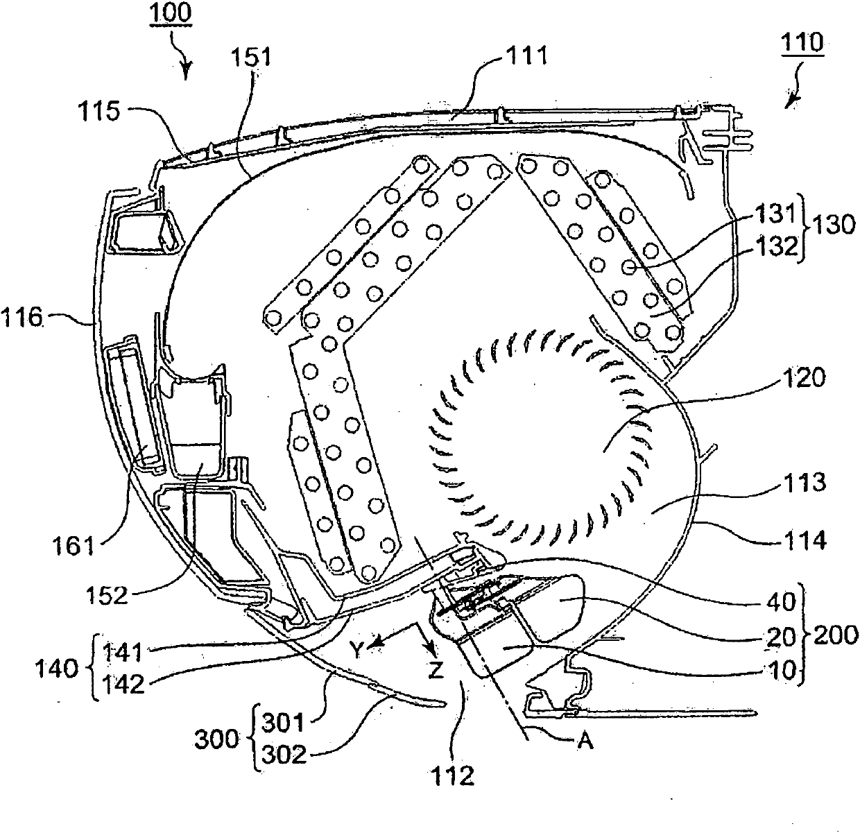
[0028] Figure 1 ~ Figure 3 It is a diagram explaining the indoor unit of the air conditioner according to the first embodiment of the present invention, figure 1 (A) is the appearance view from the front, (b) is the appearance view from directly below, figure 2 It is a perspective view showing the disassembled components, image 3 It is a cross-sectional view when viewed from the side. In addition, each drawing is a schematic drawing, and this invention is not limited by the form of illustration.

[0029] Figure 1 ~ Figure 3 Among them, an indoor unit (hereinafter referred to as "indoor unit") 100 of an air conditioner has a main body 110 provided with a suction port 111 and a blower port 112, a blower member 120 that forms an air path 113 from the suction port 111 to the blower port 112, and is arranged in The heat exchange member 130 in the air passage 113, and the left and right wind direction adjustment device (hereinafter referred t...

Embodiment approach 2

[0041] (Wind direction adjustment device)

[0042] Figure 4 ~ Figure 7 It is a diagram illustrating a wind direction adjusting device according to Embodiment 2 of the present invention, Figure 4 Is a schematic side view, Figure 5 It is a perspective view showing the disassembled components, Image 6 It is a perspective view showing the assembly situation (front blowing and diagonal blowing), Figure 7 It is a plan view (front blowing and diagonal blowing) explaining the coupling mechanism. In addition, each drawing is a schematic drawing, and this invention is not limited by the form of illustration.

[0043] Figure 4 ~ Figure 7 In the wind direction adjusting device 200, the first part 10, the second part 20, the moving part 30, the base 40, and the driving member 50 are assembled. The base 40 is installed under the drain pan 142 of the indoor unit 100 (Embodiment 1).

[0044] (First part)

[0045] The first member 10 has a reference shaft 11 and a first wind direction plate (...


PUM


Abstract

There is provided an wind direction adjusting apparatus in which an energy saving effect is obtained by restraining an increase in draft resistance, and an indoor unit of an air conditioner having the wind direction adjusting apparatus provided therein. An wind direction adjusting apparatus 200 includes a base member 40, a first wind direction plate 12 provided on the base member 40 so as to be rotatable about a reference center of rotation A, a second wind direction plate 22 provided on the first wind direction plate 12 so as to be rotatable about a coupled center of rotation B, a moving member 30 provided with the first wind direction plate 12 and the second wind direction plate 22 so as to be rotatable about a first center of rotation C and a second center of rotation D respectively, and driving means 50 configured to move the moving member 30 relatively with respect to the base member 40, and an angle formed between a first imaginary line L1 connecting the reference center of rotation A and the coupled center of rotation B and a second imaginary line L2 connecting the coupled center of rotation B and the second center of rotation D varies according to the amount of relative movement of the moving member 30.

Description

Technical field [0001] The present invention relates to a wind direction adjustment device and an indoor unit of an air conditioner, in particular, a wind direction adjustment device installed on the indoor unit of an air conditioner and an indoor unit of an air conditioner provided with the wind direction adjustment device. Background technique [0002] The air outlet of the indoor unit (the same as the indoor unit) of the air conditioner is provided with a wind direction adjusting device that adjusts the blowing direction of the cooled or heated air. This wind direction adjusting device has previously disclosed a wind direction adjusting device that includes a wind direction plate (same as a vertical blade) having a flexible portion that is free to bend, and adjusts the blowing direction by bending the soft portion (for example, refer to Patent Document 1). [0003] In addition, the following wind direction adjusting device is also disclosed. The wind direction adjusting device h...

Claims


Application Information

Patent Timeline
Patent Type & Authority Patents(China)
IPC IPC(8): F24F13/10
CPCF24F13/15F24F13/1426F24F1/0011F24F2013/1473
Inventor 石川正人大石雅之铃木章元池田久典木南雅英横田周平小柳洋平
Owner MITSUBISHI ELECTRIC CORP
Why Eureka
Try Eureka