Plasma fuel cell

A fuel cell and plasma technology, applied in fuel cells, circuits, electrical components, etc., can solve the problems of poor start-up performance and high cost of fuel cells

Inactive Publication Date: 2009-07-29
王守义
View PDF3 Cites 2 Cited by
  • Summary
  • Abstract
  • Description
  • Claims
  • Application Information

AI Technical Summary

Problems solved by technology

[0003] In order to solve the problems of high cost and poor start-up performance of existing fuel cells, the present invention proposes a plasma fuel cell

Method used


Image

  • Plasma fuel cell
  • Plasma fuel cell
  • Plasma fuel cell

Examples


Embodiment Construction

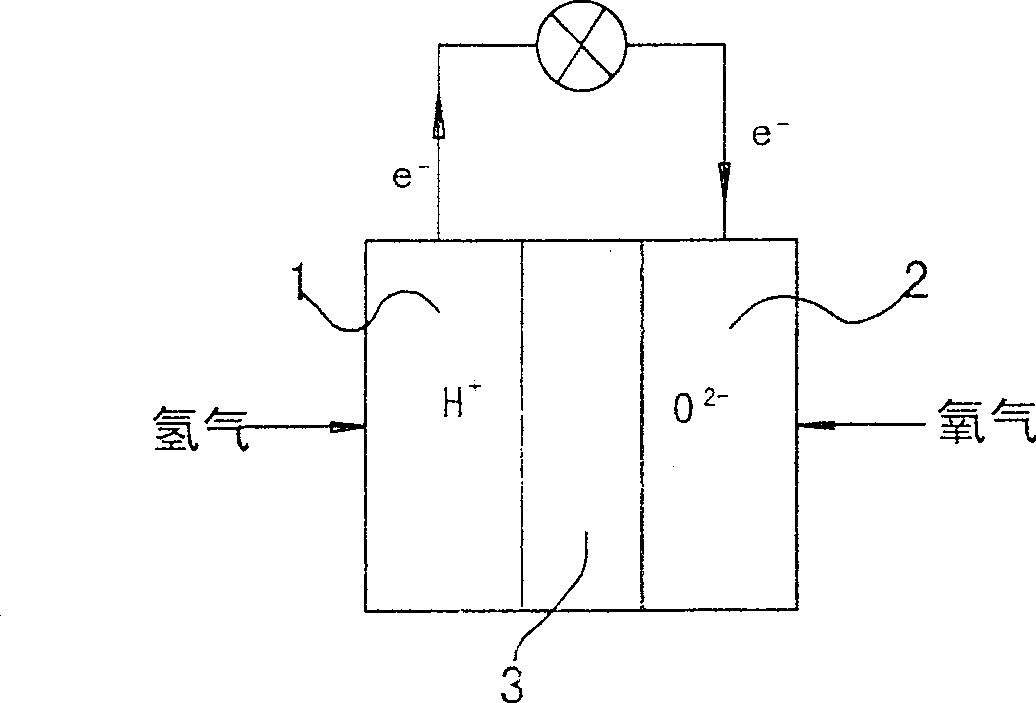
[0018] figure 1 Shown is the basic structural diagram of the existing fuel cell, the electrolyte 3 is between the left porous electrode 1 and the right porous electrode 2, and the left porous electrode 1 and the right porous electrode 2 are respectively connected as an anode and a cathode to form an output circuit; in addition, the electrodes The structure is also different, and the manufacturing process of some electrodes is very complicated. However, their basic principles are common.

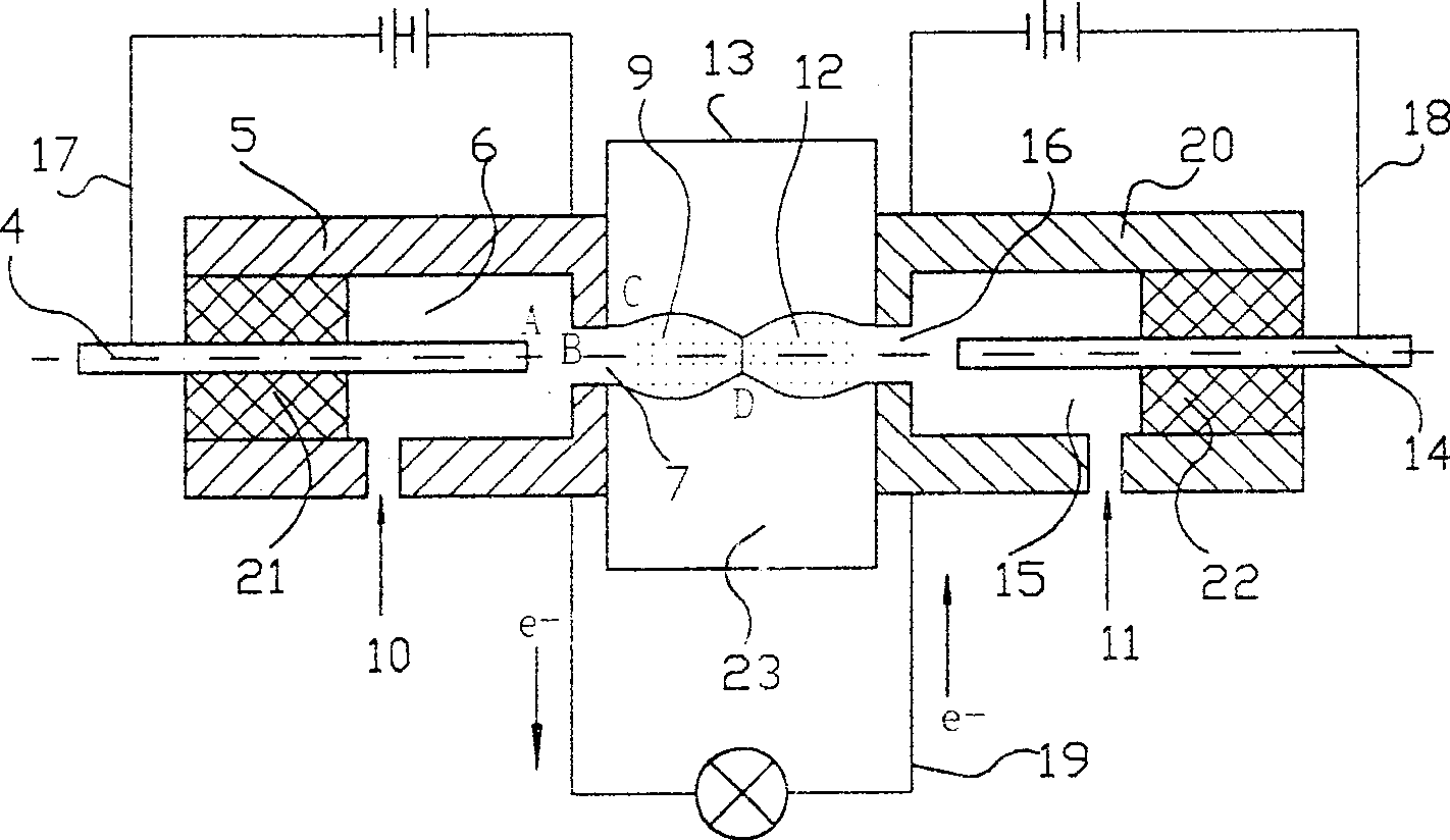
[0019] exist figure 2 Among them, the left plasma gun is composed of the left center electrode 4 and the left gun cavity wall 5. The left center electrode 4 and the left gun cavity wall 5 are separated by an insulator 21. The left gun cavity wall 5 is another electrode of the plasma gun. The left center There is also an inner cavity 6 between the electrode 4, the insulator 21 and the left gun cavity wall 5, on which a hydrogen gas inlet 10 and an injection hole 7 are arranged. The right s...


PUM


Abstract

The plasma fuel cell comprises two pieces of plasma gun for generating flame jet of plasma in high temperature and high speed. There are electrolyte or water or air between two plasma guns. Two pieces of plasma guns jet hydrogen plasma flow and oxygen plasma flow to electrolyte. Cavity walls of the said plasma guns are as anode and cathode, which are connected to form a main circuit. When two plasma flows are combined to water or CO2, current is generated in the main circuit. Comparing with prior art, the disclosed fuel cell possesses advantages: (1) higher than 60% system effectiveness; (2) simple structure, small size, low manufacturing cost, without need of large numbers of noble metal platinum, good reliability; (3) large power of single body; (4) quick starting; (5) environment protection, and various fuels including non- hydrogen fuel; (6) high overload capacity; (7) not need of large investment in wide application.

Description

technical field [0001] The invention relates to a fuel cell. Background technique [0002] Existing fuel cells have gone through five generations. They are divided into alkaline fuel cells (AFC), phosphoric acid fuel cells (PAFC), molten carbonate fuel cells (MCFC), solid oxide fuel cells (SOFC) and proton exchange membrane fuel cells (PEMFC) according to different electrolytes. Their common basic principles are figure 1 shown. There are yin and yang electrode plates, and these electrode plates have porous materials as the main components. There is an electrolyte between the two electrode plates. Most of their fuel is hydrogen. Hydrogen gas reaches the electrolyte through the micropores of the anode plate under a certain pressure. Similarly, air (oxygen) also reaches the electrolyte through the micropores of the cathode plate under a certain pressure, and then passes through the catalyst and electrolyte, where hydrogen and oxygen generate chemical ions. At the same tim...

Claims


Application Information

Patent Timeline
Patent Type & Authority Patents(China)
IPC IPC(8): H01M8/00
CPCY02E60/50Y02P70/50
Inventor 王守义
Owner 王守义
Why Eureka
Try Eureka