Electric connector and connection structure for electric connector

An electrical connector and construction technology, applied in the direction of electrical components, etc., can solve the problems of poor contact, conductor pattern and contact pressure drop of the contact part, etc.

Inactive Publication Date: 2009-07-29
JST MFG CO LTD
View PDF7 Cites 0 Cited by
  • Summary
  • Abstract
  • Description
  • Claims
  • Application Information

AI Technical Summary

Problems solved by technology

At this time, the contact pressure between the conductor pattern and the contact part decreases, which may cause poor contact.

Method used


Image

  • Electric connector and connection structure for electric connector
  • Electric connector and connection structure for electric connector
  • Electric connector and connection structure for electric connector

Examples


Embodiment Construction

[0045] Embodiments of the present invention will be described with reference to the drawings.

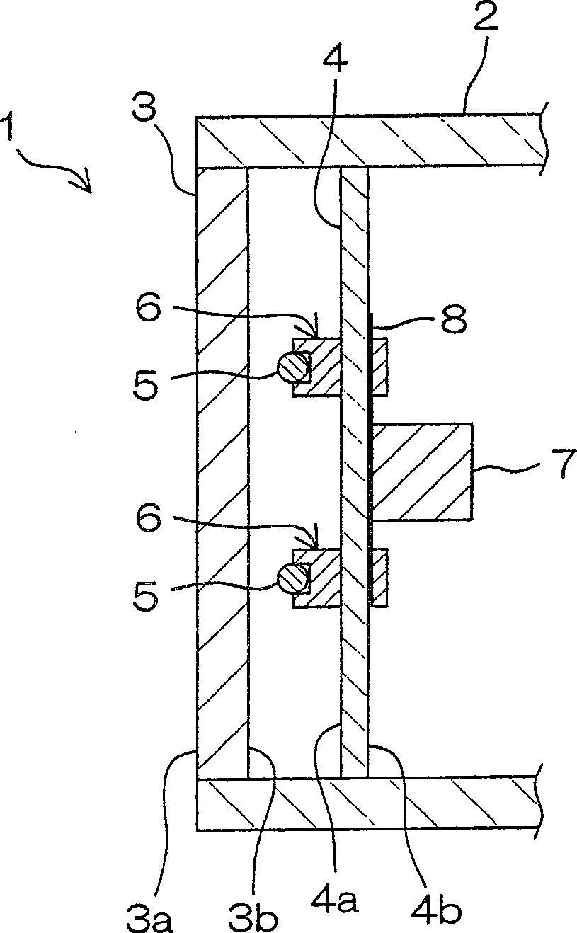
[0046] figure 1 It is a schematic cross-sectional view showing a schematic structure of an electrical connector and a liquid crystal display device having a connection structure of the electrical connector according to an embodiment of the present invention. refer to figure 1 , the liquid crystal display device 1 is used, for example, as a display of a television or a personal computer.

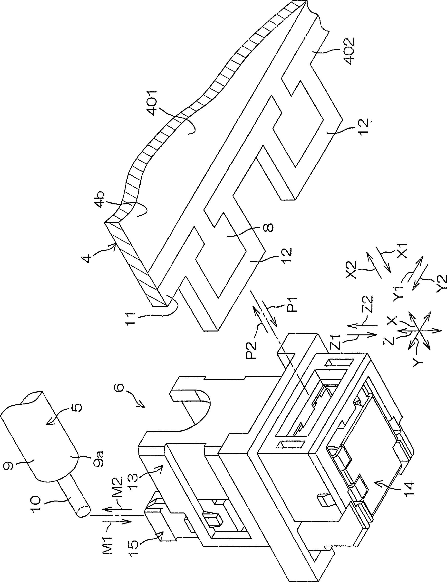
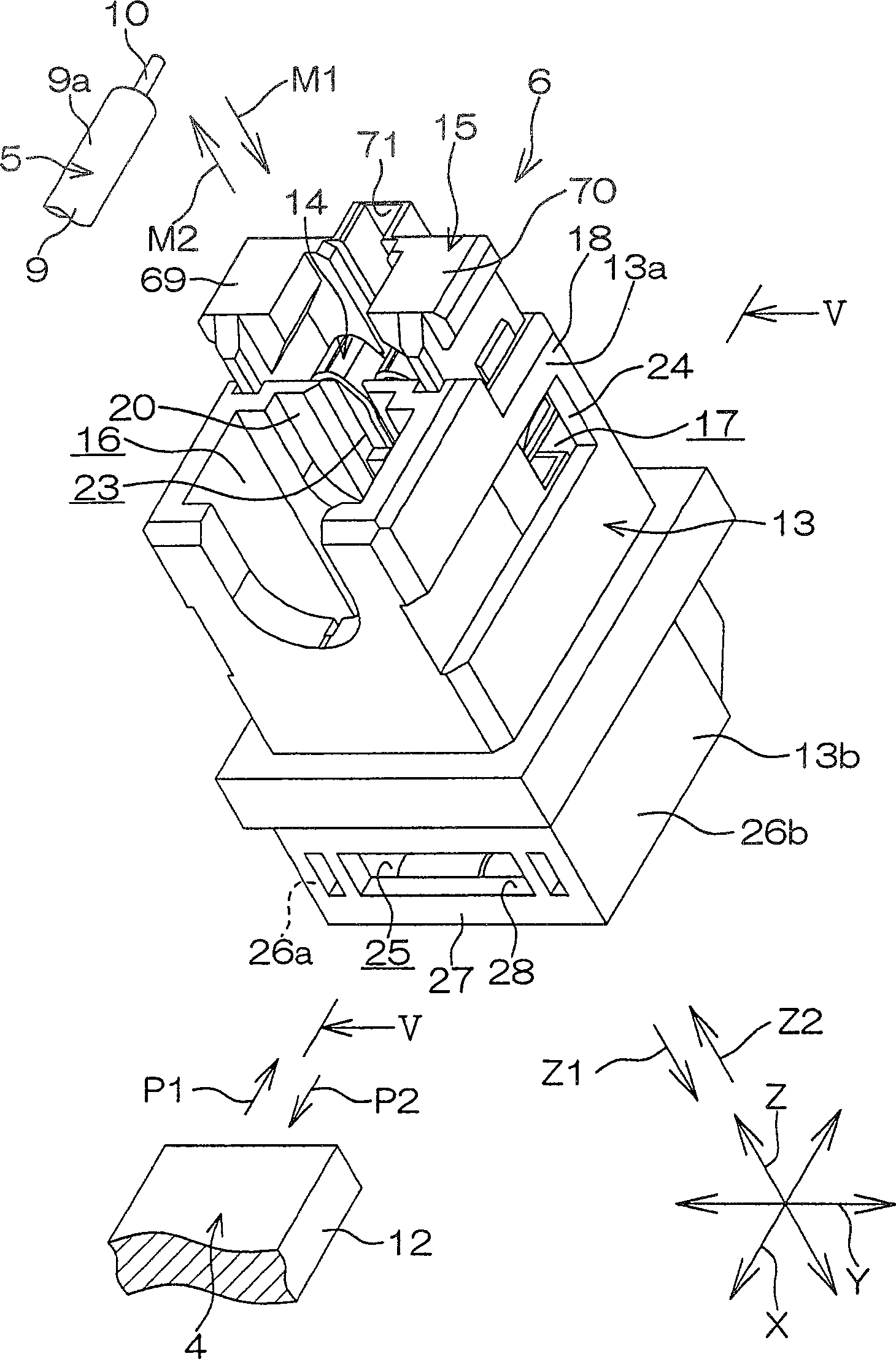
[0047] The liquid crystal display device 1 has a housing 2 , a liquid crystal panel 3 , a circuit board 4 as a connecting member, cold cathode tubes 5 as fluorescent tubes, a plurality of electrical connectors 6 , and an inverter circuit 7 . The electrical connector connection structure is formed by the circuit board 4 and the plurality of electrical connectors 6 mounted on the circuit board 4 .

[0048] The liquid crystal panel 3 is a non-self-illuminating display panel, and is mounted on the f...


PUM


Abstract

An electric connector (6) to be attached to a plate-like connection member (4; 100) having an edge portion (402; 102), a plurality of insertion convex portions (12; 103) formed sideways at the edge portion (402; 102), and a conductive portion (8; 8B; 103a, 103b) formed on at least one of the front surface (4a; 103a). The back surface (4b; 103b) of each insertion convex portion (12; 103) includes an insulating housing (13) and a contact forming member (14; 14A; 14B; 14B'; 14C; 14C'; 14D; 14E; 14F; 14G; 14H; 14J) made of a metal and held in the housing (13). The contact forming member (14; 14A; 14B; 14B'; 14C; 14C'; 14D; 14E; 14F; 14G; 14H; 14J) includes a box-like portion (33; 33D) having four.walls (41, 42, 43, 44; 41D, 42D, 43D, 44D) and a connection member connecting contact (34; 34B) extended from at least one of the walls of the box-like portion (33; 33D). The four walls (41, 42, 43, 44; 41D, 42D, 43D, 44D) define an insertion concave portion (45) into which the insertion convex portion (12; 103) corresponding thereto is inserted along a predetermined insertion direction (P1). The connection member connecting contact (34; 34B) includes a contact portion (475; 475A; 475B; 475C; 475D; 475E; 475F; 475G; 475J) that makes contact with the conductive portion (8; 8B; 103a, 103b) of the corresponding insertion convex portion (12; 103) inserted into the insertion concave portion (45).

Description

technical field [0001] The present invention relates to an electrical connector and a connection structure of the electrical connector. Background technique [0002] Generally, an electrical connector has a synthetic resin housing and metal contacts held in the housing (see, for example, Document 1 below). [0003] Document 1: JP-A-2000-331732 (published date: November 30, 2000). [0004] The contact has a base portion fixed to the housing, an elongated bent portion extending in an S-shape from the base portion, and a protruding contact portion provided at a tip of the bent portion. The contact portion contacts and presses a conductor pattern formed on the surface of the circuit board. Accordingly, the bent portion elastically deforms, and an elastic repulsive force is applied to the conductor pattern from the bent portion. According to this, a contact pressure is generated between the contact portion and the conductor pattern. [0005] A receiving portion facing the con...

Claims


Application Information

Patent Timeline
Patent Type & Authority Patents(China)
IPC IPC(8): H01R12/32H01R12/16
Inventor 半田真介宫园克则
Owner JST MFG CO LTD
Why Eureka
Try Eureka