Valve and method for producing a valve

A valve seat and valve body technology, which is applied in the field of valve and valve manufacturing, can solve the problems of dirt particles polluting the valve seat, the valve seat is not sealed, and the valve seat is not sealed, and achieves the effect of reducing the risk of polluting the valve seat.

Active Publication Date: 2009-08-05
ZHEJIANG SANHUA INTELLIGENT CONTROLS CO LTD
View PDF8 Cites 0 Cited by
  • Summary
  • Abstract
  • Description
  • Claims
  • Application Information

AI Technical Summary

Problems solved by technology

Even with a copper layer there may be inaccuracies in the shape of the seat which would cause the valve to leak during operation
[0006] In addition, dirt particles may contaminate the valve seat during manufacture and installation of the valve, which can also cause the valve seat to leak during operation

Method used


Image

  • Valve and method for producing a valve
  • Valve and method for producing a valve

Examples


Embodiment Construction

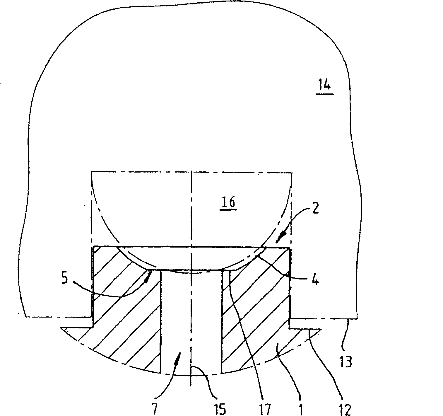
[0033] figure 1 A detail of a pole shoe 1 with a valve seat 2 and a stamping element 16 is schematically shown in . Shown here is the state of the valve seat 2 immediately before or during the stamping process. The recess 4 of a pole piece 1 or valve seat element 1 is preferably produced by turning before stamping, in which case a bead or annular plate 5 with a stamping surface 17 is formed.

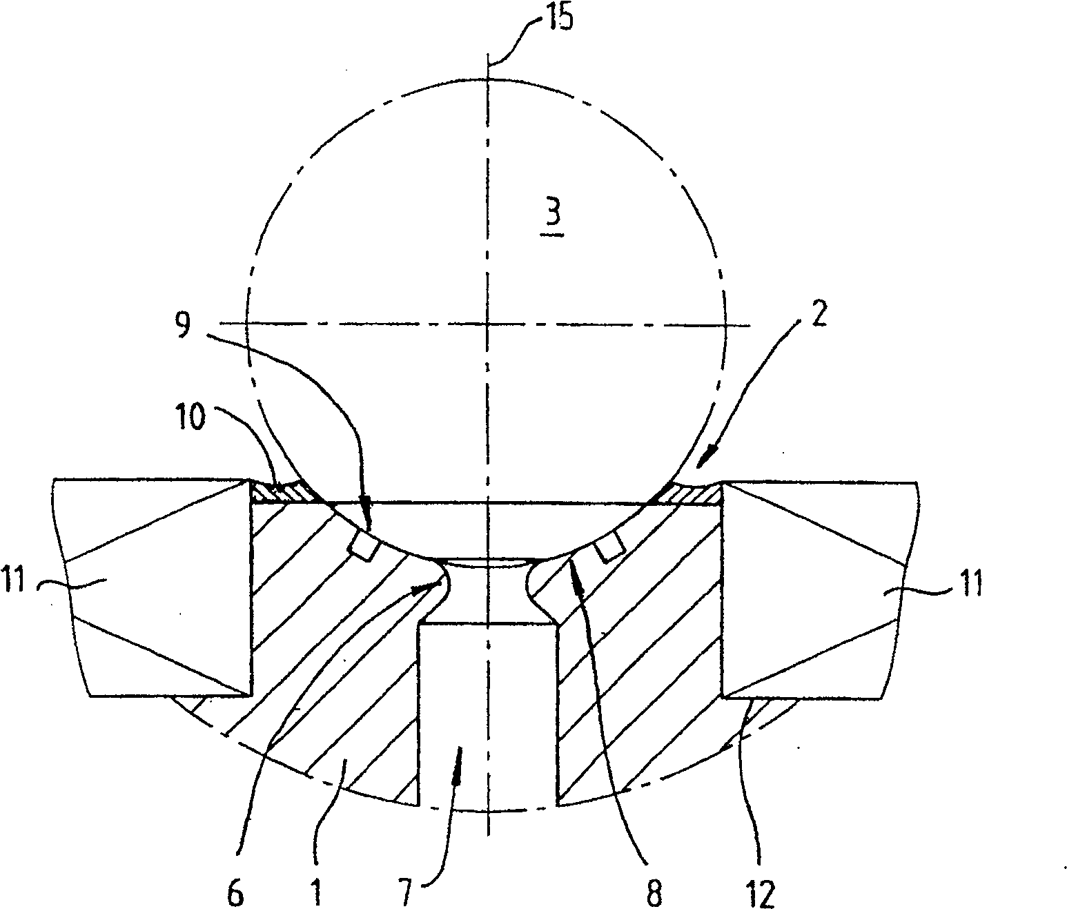
[0034] exist figure 2 The valve seat 2 after the stamping process is schematically shown in . A deformation 6 of the pole piece 1 is produced by the embossing from the projection or the annular plate 5 . It can be seen from the figure that the deformed portion 6 narrows or inflates a valve hole 7 .

[0035] Furthermore, a sealing surface 8 is formed by stamping the valve seat 2 . The sealing surface 8 forms the contact surface between the valve body 3 and the pole piece 1 . The punching is made into a spherical ring as the sealing surface 8 , and the sealing surface has high preci...


PUM


Abstract

The method involves forming a sealing surface of a valve sealing unit (1) by stamping a valve seat or pole show with a stamping unit. The stamping unit is utilized corresponding to a part of a form of a valve body. A recess is formed on the stamping surface before the stamping operation and corresponds to the form of the valve body. A projection (5) is provided on the valve seating unit before the stamping operation. An independent claim is also included for a valve of a coolant circuit.

Description

technical field [0001] The present invention relates to a valve and a method of manufacturing the valve. Background technique [0002] Different valves are currently available on the market. For example, there are electromagnetic, especially bistable valves, which are used in a wide variety of applications, for example in fluid circulation circuits in domestic appliances such as refrigerators, or in steam expansion in beverage machines such as coffee machines (Dampfentspannung), but can also be used in other fields, eg in the field of analysis or measurement technology. [0003] In most applications, including applications such as domestic appliances, it is preferred here to use valves which have a compact design and which can also be produced and installed with as little effort as possible. To facilitate this purpose, various design developments are known (cf. DE19914972A1 or WO03 / 071176A1). [0004] The known valves firstly have a valve seat which is sealed off by the v...

Claims


Application Information

Patent Timeline
Patent Type & Authority Patents(China)
IPC IPC(8): B21K1/20B21K1/24B21D22/02F16K1/14F16K1/42F16K29/00F16K31/06F16K31/08
CPCF16K29/00Y10T137/0491Y10T137/0508F16K31/084Y10T29/49409
Inventor H·H·奥特
Owner ZHEJIANG SANHUA INTELLIGENT CONTROLS CO LTD
Why Eureka
Try Eureka