

Oscillator circuit
An oscillator and oscillator circuit technology, applied in the field of oscillator circuits and high-frequency oscillator circuits, can solve problems such as increasing frequency limits, and achieve the effects of improving phase noise and increasing tuning range.
- Summary
- Abstract
- Description
- Claims
- Application Information
AI Technical Summary
Problems solved by technology
Method used
Image

Examples
Embodiment Construction
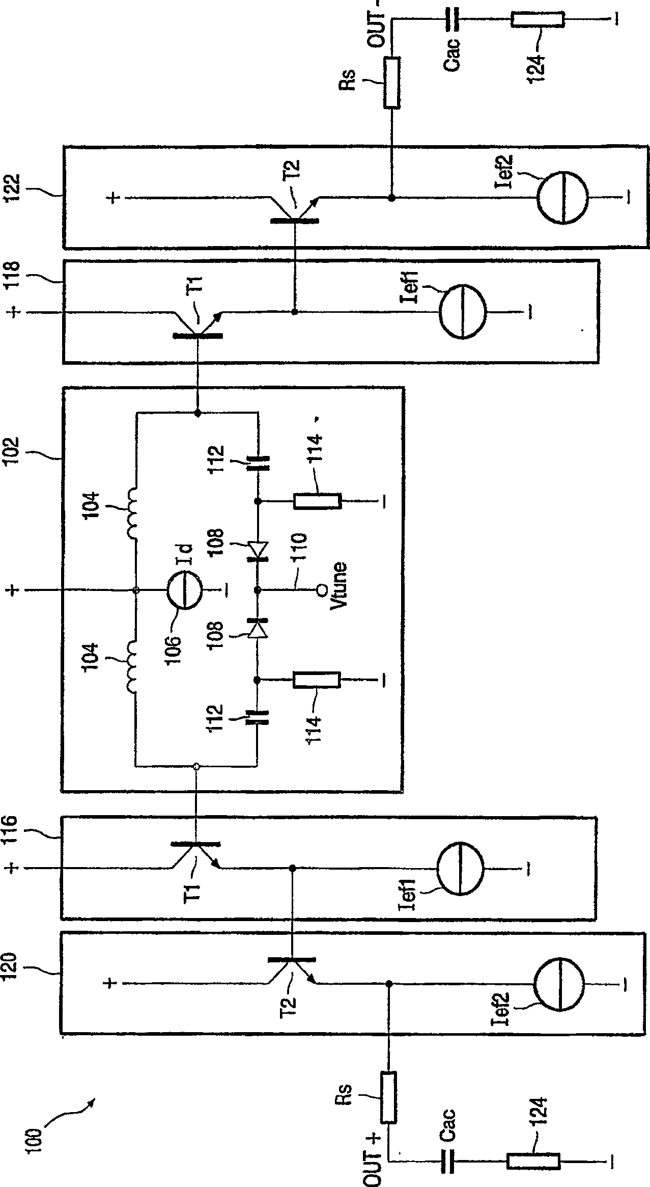
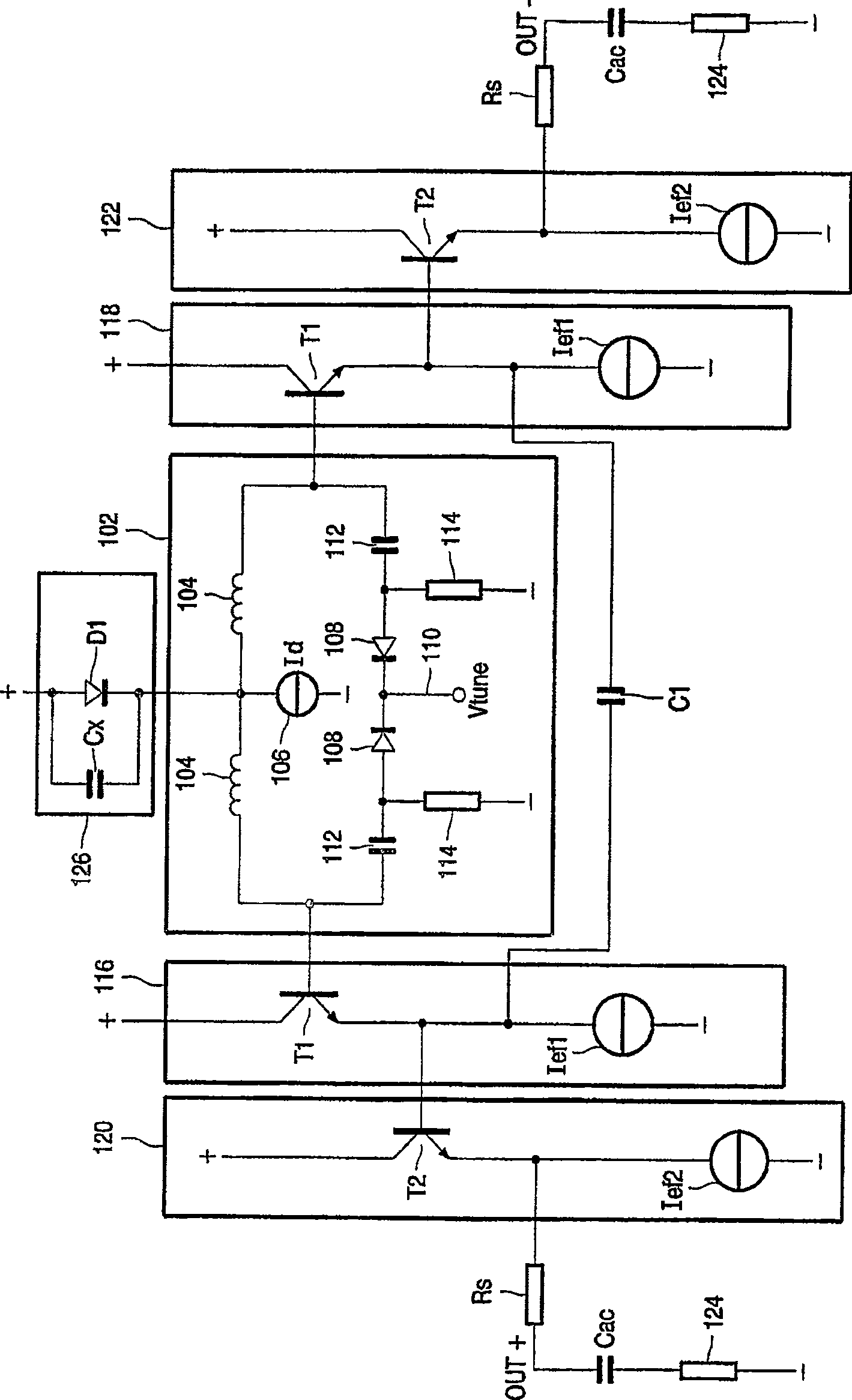
[0031] figure 1 An oscillator circuit 100 having a resonator 102 is shown. In the example considered here, the resonator 102 has an inductor 104 symmetrically coupled to a current source 106 supplying a current Id; another inductor 104 symmetrically coupled to the supply voltage. The resonator 102 has a varactor 108 with a control terminal 110 for applying a tuning voltage Vtune for frequency modulation. Capacitor 112 is coupled in series with varactor 108 . Preferably, capacitor 112 has a high value and thus a low series resistance. Therefore, the anode of the varactor 108 is DC grounded through the high ohmic series resistor 114, and the cathode, the control terminal 110, can be tuned from zero volts to the supply voltage. The bottom plate of the varactor is a common mode. This technique allows the largest possible tuning range within the mains voltage. Resonator 110 is of the common cathode type, whereby the anode of resonator 102 is coupled to emitter followers 116 an...
PUM
 Abstract
Description
Claims
Application Information