Film bulk acoustic-wave resonator and method for manufacturing the same

A technology of piezoelectric resonators and manufacturing methods, applied in the direction of electrical components, impedance networks, etc., can solve the problems of longer processing time, shift of resonance frequency, deterioration of resonance, etc., and achieve the effect of easy film thickness control

Inactive Publication Date: 2009-08-12
KK TOSHIBA
View PDF3 Cites 0 Cited by
  • Summary
  • Abstract
  • Description
  • Claims
  • Application Information

AI Technical Summary

Problems solved by technology

When the film thickness is beyond the optimum thickness, the resonant frequency shifts, and at the same time, the electromechanical coupling coefficient k, which is the strength index of piezoelectricity, is caused. t 2 reduction of the resonance, deterioration of the Q value indicating the sharpness of resonance, etc., so there is a limit to increasing the film thickness in order to obtain a margin for over-etching
In addition, if the corrosion rate is reduced to detect the end point, the processing time per time becomes longer, resulting in a decrease in productivity.

Method used


Image

  • Film bulk acoustic-wave resonator and method for manufacturing the same
  • Film bulk acoustic-wave resonator and method for manufacturing the same
  • Film bulk acoustic-wave resonator and method for manufacturing the same

Examples


no. 1 Embodiment approach

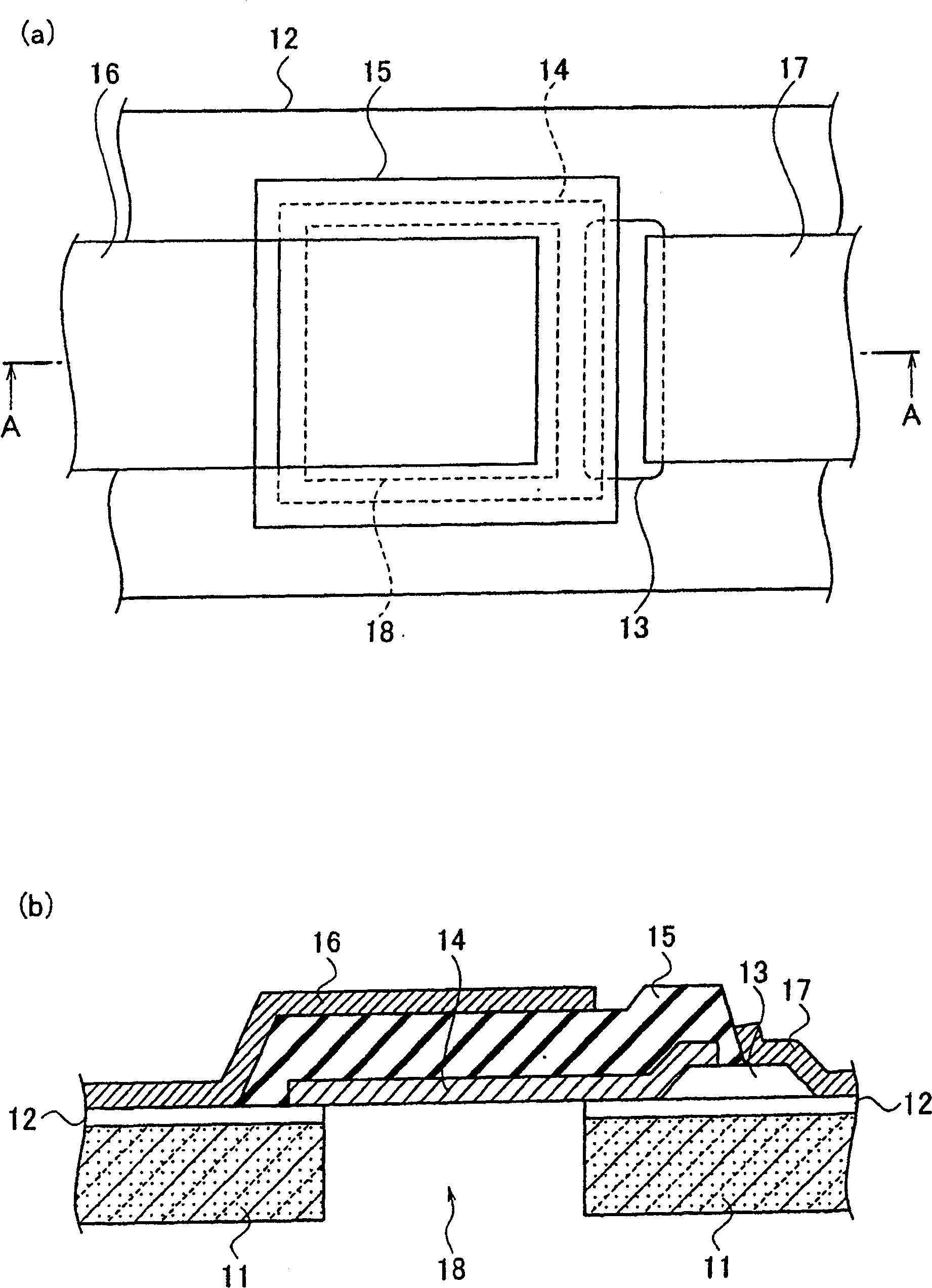
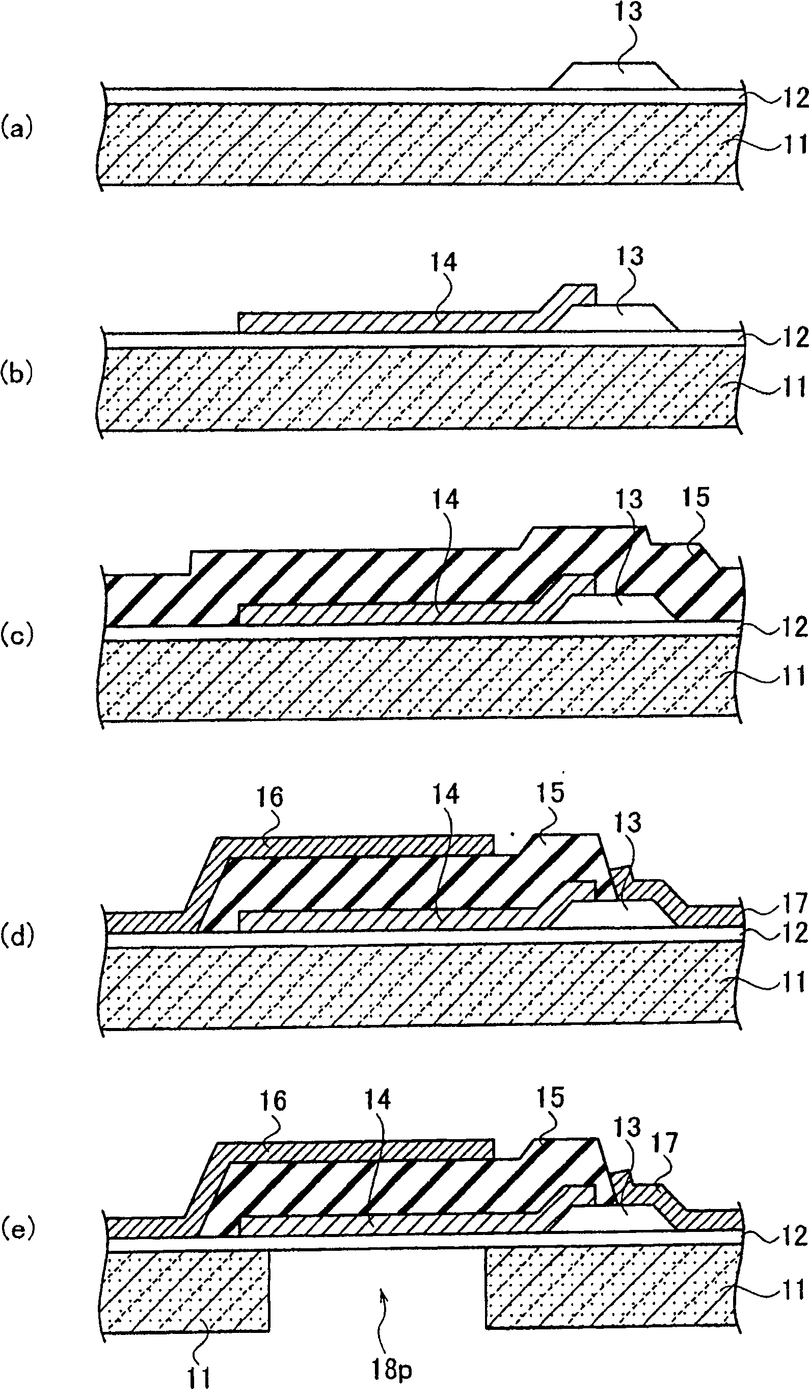
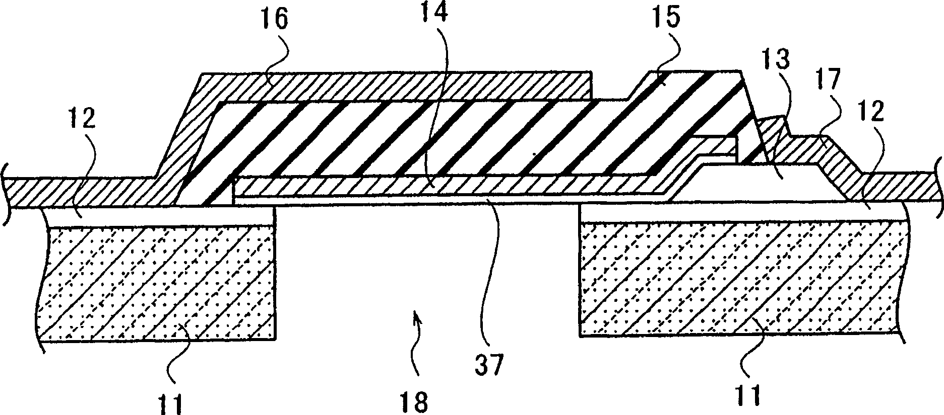
[0053] Such as figure 1 As shown, the thin film piezoelectric resonator according to the first embodiment of the present invention includes: (1) a substrate 11; (2) a lower electrode (14), a part facing the substrate 11 is hollow and mechanically held; (3) The piezoelectric body 15 is arranged on the lower electrode 14 so that it contains all the lower electrodes 14 in the area occupied by itself on a planar figure; (4) the upper electrode 16 is on the piezoelectric body 15; (5) ) The relay electrode 13, between the substrate 11 and the piezoelectric body 15, is located on the boundary of the occupied area of ​​the piezoelectric body 15 on a planar figure, and is connected to the lower electrode 14 inside the occupied area; (6) the lower part The electrode wiring 17 extends from the boundary of the occupied area to the outside, and is connected to the relay electrode 13 . Furthermore, bulk vibration in the thickness direction of the piezoelectric body 15 is utilized.

[0054...

no. 2 Embodiment approach

[0089] Such as Figure 10 As shown, the thin film piezoelectric resonator according to the second embodiment of the present invention includes: a substrate 11; an insulating film 12 formed on the substrate 11; a cavity (cavity) 19 passes through the insulating film 12, a part of which is hollow and Mechanically held lower electrode 14; a relay electrode 13 electrically connected to the lower electrode 14, which is partially laminated on one end of the lower electrode 14; formed between the lower electrode 14 and the relay electrode 13 The upper piezoelectric body 15 ; the upper electrode 16 formed on the piezoelectric body 15 ; and the lower electrode wiring 17 electrically connected to the relay electrode 13 . exist Figure 10 Only the sectional view is shown in the figure, and the plane figure is basically the same as figure 1 (a) is the same and the illustration is omitted. However, the piezoelectric body 15 includes all the lower electrodes 14 within the area occupied b...

no. 3 Embodiment approach

[0104] Such as Figure 12 As shown, the thin film piezoelectric resonator according to the third embodiment of the present invention includes: a substrate 11; an insulating film 12 formed on the substrate 11; The relay electrode 23 of the U-shaped groove; the lower electrode 14 formed on the insulating film 12 and the relay electrode 23; the piezoelectric body 15 formed on the lower electrode 14 and the relay electrode 23; An upper electrode 16 formed on the piezoelectric body 15 ; and a lower electrode wiring 17 electrically connected to the relay electrode 23 . exist Figure 12 Only the sectional view is shown in the figure, and the plane figure is basically the same as figure 1 (a) Similarly, illustration is omitted. However, the piezoelectric body 15 includes all the lower electrodes 14 within the area occupied by the piezoelectric body 15 in a plan view. And, with figure 1 The plane figure shown in (a) is the same, the boundary of the occupied area of ​​the piezoelec...


PUM


Abstract

Provided is a thin film piezoelectric resonator and a manufacturing method thereof, in which the electromechanical coupling coefficient kt2 and the Q value are simultaneously increased, and the film thickness control of the lower electrode is easy. The thin-film piezoelectric resonator includes: a substrate (11); a lower electrode (14), a part facing the substrate (11) is hollow and mechanically held; a piezoelectric body (15) is arranged on the lower electrode (14) , so that it contains all the lower electrodes (14) in the area occupied by itself on the plane figure; the upper electrode (16) is on the piezoelectric body (15); the relay electrode (13) is on the substrate Between (11) and the piezoelectric body (15), on the planar figure, it is located at the boundary of the occupied area of ​​the piezoelectric body (15), and is connected with the lower electrode (14) inside the occupied area; and the lower electrode wiring ( 17), extending from the boundary of the occupied area to the outside, connected to the relay electrode (13).

Description

technical field [0001] The present invention relates to a thin-film piezoelectric resonator, and more particularly to a thin-film piezoelectric resonator that utilizes longitudinal vibration in the thickness direction of a piezoelectric thin film and a method for manufacturing the same, which can be used as a high-frequency filter or a high-frequency oscillator. Background technique [0002] In recent years, the wireless center technology has been developed by leaps and bounds, especially the development for the purpose of high-speed transmission continues. With the increase in the amount of information transmitted and the further increase in frequency, the requirements for miniaturization and light weight of high-frequency communication devices are even stronger. A wireless device is generally roughly divided into an RF front-end section that processes high frequency (RF), and a baseband (BB) section that performs digital signal processing. Among them, the BB part is a par...

Claims


Application Information

Patent Timeline
Patent Type & Authority Patents(China)
IPC IPC(8): H03H9/13H03H9/17H03H3/02
Inventor 佐野贤也梁濑直子板谷和彦安本恭章尾原亮一川久保隆罇贵子
Owner KK TOSHIBA
Why Eureka
Try Eureka