Outside folding umbrella structure

A structure and umbrella technology, applied in the field of external umbrella structure, to achieve the effect of improving the convenience and practicability of use

Inactive Publication Date: 2009-08-26
王煌麟
View PDF11 Cites 0 Cited by
  • Summary
  • Abstract
  • Description
  • Claims
  • Application Information

AI Technical Summary

Problems solved by technology

[0003] Generally speaking, the above-mentioned umbrella structure in the prior art has the following disadvantages, for example: because the water droplets remaining on the outer surface of the umbrella part are also easy to escape or splash along the umbrella surface to the user when opening and closing. on the body

Method used


Image

  • Outside folding umbrella structure
  • Outside folding umbrella structure

Examples


Embodiment Construction

[0009] In order to make the above-mentioned and other purposes, features and advantages of the present invention more obvious and understandable, the preferred embodiments of the present invention are specifically cited below, combined with the accompanying drawings, as follows:

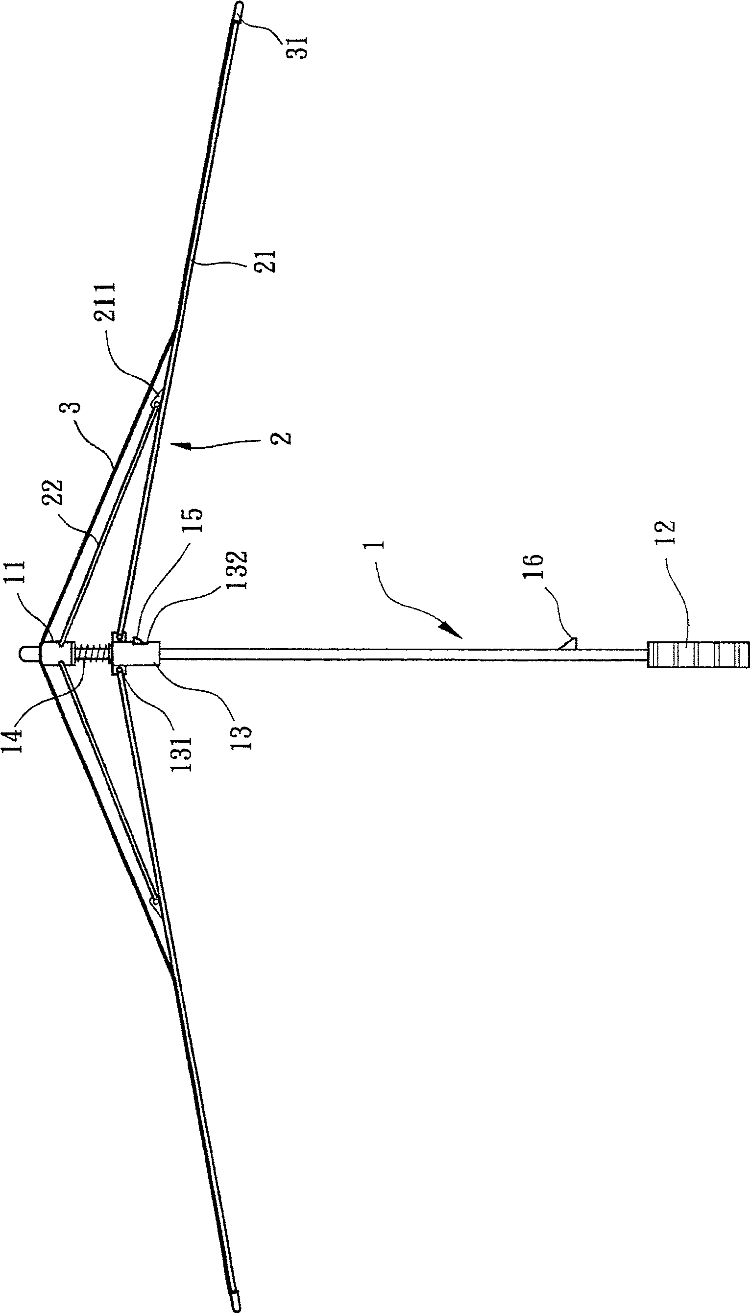
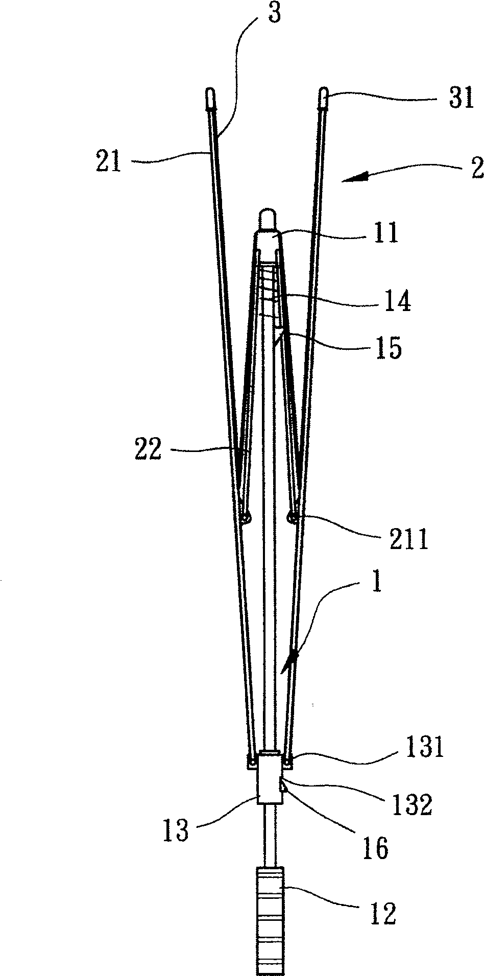
[0010] Please refer to figure 1 As shown, the outer umbrella structure of the preferred embodiment of the present invention includes a main rod body 1 , several umbrella ribs 2 and an umbrella cloth 3 . The main rod body 1 includes a fixed hub 11 , a handle 12 , a sliding part 13 , an elastic component 14 and a locking part 15 . The fixed hub 11 is arranged on one end of the main rod body 1; the handle 12 is arranged on the other end of the main rod body 1 relative to the fixed hub 11; The sliding member 13 is provided with several pivoting protrusions 131 and a locking hole 132, wherein the several pivoting protrusions 131 are arranged around the outer periphery of the sliding member 13; the elasti...


PUM


Abstract

The present invention relates to an improved umbrella structure. Said improved umbrella structure includes the following several portions: a main bar body, several spreader components, an umbrella cloth, a fixed hub, a slide component and a handle. Said invention also provides the connection mode of all the above-mentioned portions and the concrete operation method of said improved umbrella structure.

Description

technical field [0001] The present invention relates to an external umbrella structure, in particular to a kind of pivotably connecting one end of several main ribs to a sliding part, and pivotably connecting two ends of several auxiliary ribs to a fixed hub respectively. It is connected with the main umbrella rib, which effectively reduces the possibility of residual water droplets splashing on the user when it is opened or folded. Background technique [0002] The umbrella structure of the prior art, as described in the new patent No. 395195 "umbrella structure improvement" in Taiwan, China, comprises a main rod, a handle, a fixed hub, a sliding part, several main ribs, several Deputy umbrella ribs and an umbrella cloth. The two ends of the main rod are respectively provided with the handle and the fixed hub. The outer periphery of the fixed hub is radially provided with several pivoting fulcrums. The sliding part is movably sleeved on the middle section of the main rod...

Claims


Application Information

Patent Timeline
Patent Type & Authority Patents(China)
IPC IPC(8): A45B23/00A45B25/02A45B25/06
Inventor 王煌麟
Owner 王煌麟
Why Eureka
Try Eureka