Stop valve capable of dynamically sampling

A shut-off valve, dynamic technology, applied in the field of shut-off valves that can be dynamically sampled, can solve the problems of troublesome operation, small friction, large fluid resistance, etc.

Active Publication Date: 2022-03-04
浙江瑞通阀门有限公司
View PDF13 Cites 0 Cited by
  • Summary
  • Abstract
  • Description
  • Claims
  • Application Information

AI Technical Summary

Problems solved by technology

[0002] Globe valve, also called cut-off valve, is one of the most widely used valves. The reason why it is popular is that the friction between the sealing surfaces is small during the opening and closing process, it is relatively durable, the opening height is not large, and it is easy to manufacture. , easy maintenance, not only suitable for medium and low pressure, but also suitable for high pressure. The closing principle of the globe valve is to rely on the pressure of the valve rod to make the sealing surface of the valve disc and the sealing surface of the valve seat fit closely to prevent the flow of medium. my country's valve "three modernizations" "Give" has stipulated that the flow direction of the globe valve should be from top to bottom, so there is directionality during installation. The structural length of the globe valve is larger than that of the gate valve. At the same time, the fluid resistance is large, and the sealing reliability is not strong during long-term operation.
[0003] In order to determine the parameters of the fluid medium in the shut-off valve channel, it is necessary to sample it, but the shut-off valve will seal the flow channel in a fully closed state, and sampling cannot be performed. If sampling is performed when the shut-off valve is idle, it is necessary to disassemble the valve connected to the shut-off valve. The pipeline is then sampled, which is very troublesome to operate

Method used


Image

  • Stop valve capable of dynamically sampling
  • Stop valve capable of dynamically sampling
  • Stop valve capable of dynamically sampling

Examples


Embodiment

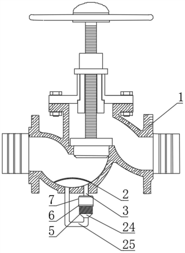
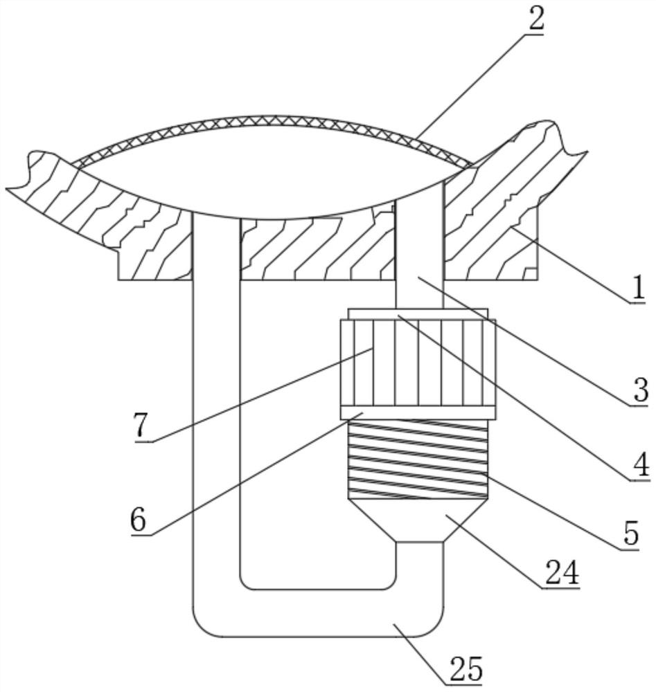
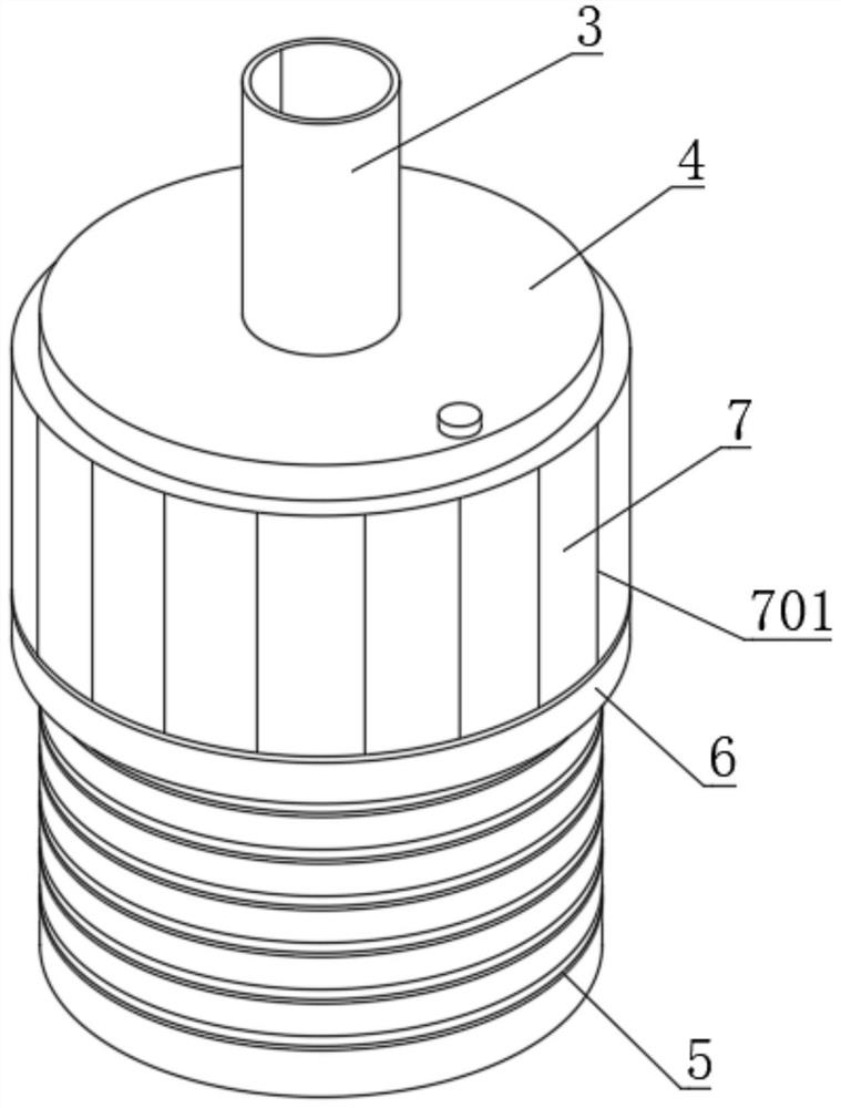
[0041] see Figure 1-6 , a globe valve capable of dynamic sampling, comprising a valve body 1, the inner bottom end of the valve body 1 is fixedly connected with an arc-shaped filter screen 2, and the inner bottom end of the valve body 1 is fixedly connected with a shunt pipe 3, and the shunt pipe 3 is located on the arc Below the filter screen 2, the lower end of the shunt pipe 3 is fixedly connected with an engaging column 4, and the outer peripheral surface of the connecting column 4 is dug with a thread groove 5, and the outer peripheral surface of the connecting column 4 is threadedly connected with an engaging ring 6, and the connecting ring 6 The upper end is fixedly connected with a sealing ring 7, and the inner wall of the sealing ring 7 is fixedly connected with a rubber extruded layer 8. The inner wall of the rubber extruded layer 8 fits the outer peripheral surface of the connecting column 4, and the outer peripheral surface of the connecting column 4 is excavated a...


PUM

PropertyMeasurementUnit
Thicknessaaaaaaaaaa

Abstract

The invention discloses a stop valve capable of dynamically sampling, and belongs to the field of stop valves, the stop valve capable of dynamically sampling comprises a valve body, when water flow circulates in an accumulation hopper and a return pipe, the circulation speed of water is accelerated through a spiral rifling, the accelerated water flow enters the valve body again through a one-way water outlet, and when the water flow enters the valve body again, the flow speed of the water flow is increased. The acceleration impact force can break the static state of the water flow, so that undercurrent is formed in the water flow for continuously maintaining real-time'dynamic updating 'of the water flow in the inner cavity of the sampling vessel, and due to the existence of the one-way water outlet, the water flow in the valve body cannot enter the return pipe from the water outlet end of the return pipe, so that the water flow in the return pipe has one-way circulation performance; the impact force carried by the accelerated water flow can impact the arc-shaped filter screen, the possibility that impurities adhere to the surface of the arc-shaped filter screen for a long time is reduced, the filtering effect of the arc-shaped filter screen is improved, and meanwhile the possibility that the arc-shaped filter screen is blocked is reduced.

Description

technical field [0001] The invention relates to the field of stop valves, in particular to a stop valve capable of dynamic sampling. Background technique [0002] Globe valve, also called cut-off valve, is one of the most widely used valves. The reason why it is popular is that the friction between the sealing surfaces is small during the opening and closing process, it is relatively durable, the opening height is not large, and it is easy to manufacture. , easy maintenance, not only suitable for medium and low pressure, but also suitable for high pressure. The closing principle of the globe valve is to rely on the pressure of the valve rod to make the sealing surface of the valve disc and the sealing surface of the valve seat fit closely to prevent the flow of medium. my country's valve "three modernizations" It has been stipulated that the flow direction of the stop valve should be from top to bottom, so there is directionality during installation. The structural length of t...

Claims


Application Information

Patent Timeline
IPC IPC(8): F16K1/02B01D29/00B01D35/04G01N1/10
CPCF16K1/02B01D29/0097B01D35/04G01N1/10
Inventor 朱华峰陈希陈思徐进杰朱金娟夏小涵
Owner 浙江瑞通阀门有限公司
Why Eureka
Try Eureka