Flue gas combined desulfurization and denitration method

A technology for desulfurization, denitrification and flue gas, which is applied in separation methods, chemical instruments and methods, and air quality improvement. Effect

Inactive Publication Date: 2009-09-02
ZHEJIANG UNIV
View PDF5 Cites 0 Cited by
  • Summary
  • Abstract
  • Description
  • Claims
  • Application Information

AI Technical Summary

Problems solved by technology

[0007] The invention provides a flue gas combined desulfurization and denitrification method, which effectively improves the oxidation degree of flue gas nitrogen oxides by using photocatalytic technology, and effectively solves the problem of low absorption efficiency of nitrogen oxides by the double alkali method

Method used

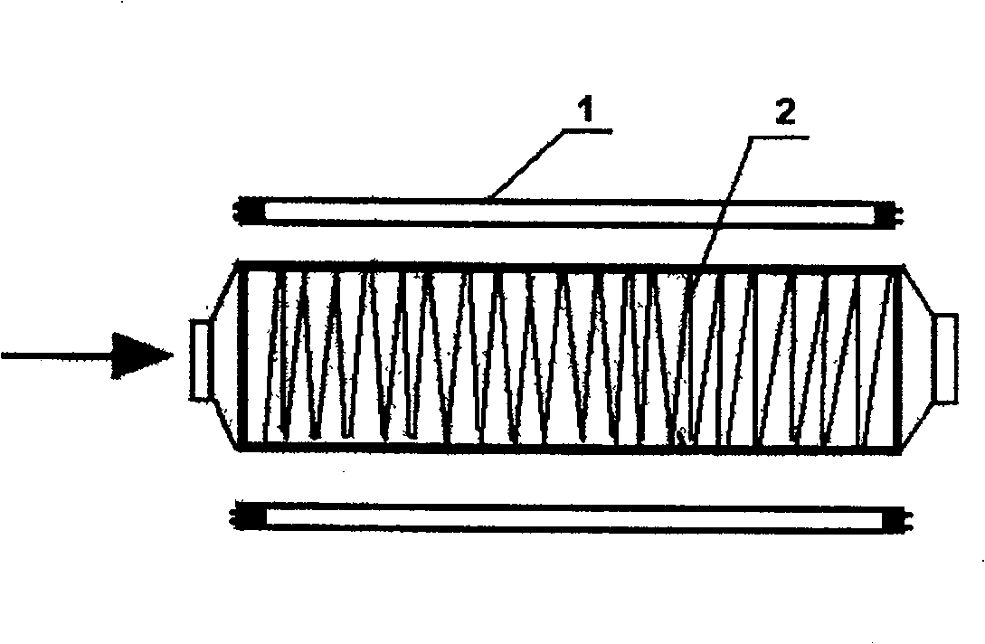
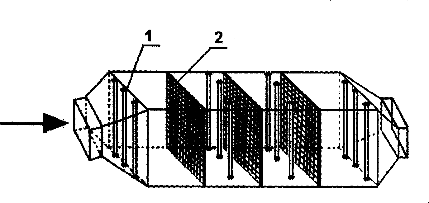
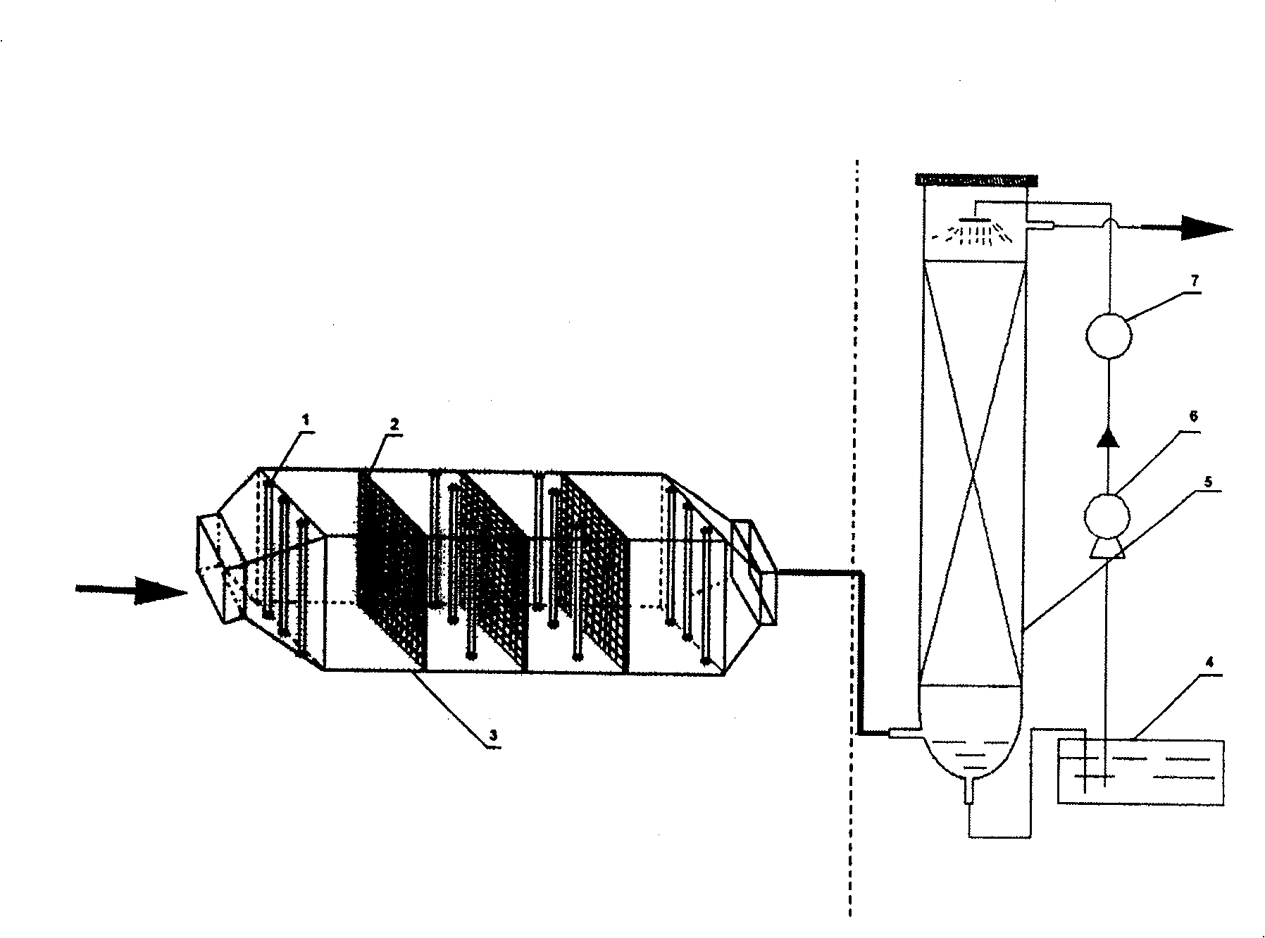

Image

  • Flue gas combined desulfurization and denitration method
  • Flue gas combined desulfurization and denitration method
  • Flue gas combined desulfurization and denitration method

Examples


Embodiment 1

[0047] Preparation of Glass Fiber Supported TiO by Coating Method 2 Immobilized catalyst, the catalyst loading is 0.7mg / cm 2 ; The loaded catalyst is stacked in the catalytic reactor. SO in the imported flue gas 2 The concentration is 1500mg / m 3 , NOx concentration is 600mg / m 3 . The sodium ion concentration of the absorption liquid is 0.1 mol / L, pH=6.0. The flue gas to be treated enters the photocatalytic reactor for photocatalytic oxidation reaction. After testing, NO in the flue gas nitrogen oxide 2 content from about 10% to more than 50%. The oxidized flue gas enters the absorption reactor and fully contacts with the absorption liquid. The test results of the discharged flue gas show that the desulfurization efficiency of 90% and the denitrification efficiency of 60% can be achieved.

Embodiment 2

[0049] Preparation of Glass Fiber Supported TiO by Coating Method 2 Immobilized catalyst, the catalyst loading is 1.0mg / cm 2 ; The loaded catalyst is stacked in the catalytic reactor. SO in the imported flue gas 2 The concentration is 1200mg / m 3 , NOx concentration is 500mg / m 3 . The sodium ion concentration of the absorption liquid is 0.1 mol / L, pH=6.0. The flue gas to be treated enters the photocatalytic reactor for photocatalytic oxidation reaction. After testing, NO in the flue gas nitrogen oxide 2 content from about 10% to more than 50%. The oxidized flue gas enters the absorption reactor and fully contacts with the absorption liquid. The test results of the discharged flue gas show that the desulfurization efficiency of 95% and the denitrification efficiency of 70% can be achieved.

Embodiment 3

[0051] Preparation of Glass Fiber Supported TiO by Coating Method 2 Immobilized catalyst, the catalyst loading is 1.5mg / cm 2 ; The loaded catalyst is stacked in the catalytic reactor. SO in the imported flue gas 2 The concentration is 1200mg / m 3 , NOx concentration is 200mg / m 3 . The sodium ion concentration of the absorption liquid is 0.1 mol / L, pH=6.0. The flue gas to be treated enters the photocatalytic reactor for photocatalytic oxidation reaction. After testing, NO in the flue gas nitrogen oxide 2 content from about 10% to more than 75%. The oxidized flue gas enters the absorption reactor and fully contacts with the absorption liquid. The test results of the discharged flue gas show that the desulfurization efficiency of 90% and the denitrification efficiency of 90% can be achieved.


PUM


Abstract

The invention discloses a method for flue gas combined desulfurizing and denitrifying. The pending flue gas enters into the photocatalytic reactor to transmute the NO in the flue gas into NO2 at the function of ultraviolet light and catalyst. The flue gas oxidated enters into double alkali reactor, where the SO2 in the flue gas is absorbed by alkali, the Na2SO3 in the resultant reacts with NO2 in the flue gas, and N2 is exhausted out after reduced from NO2. The NO in the flue gas is done photochemical catalytic oxidation using TiO2 in the invention process to oxidate the NO into NO2 rapidly and enhance the oxidation degree of the NOx in the flue gas. The Na2SO3 produced in the process of double alkali desulfurization is used as a reducing absorption liquid to realize wet desulfurization and denitration at the same time. The efficiency of desulfurization and denitration is high, the structure is simple, and operation is convenient and the occupation of land is small.

Description

technical field [0001] The invention relates to the technical field of air pollution control, in particular to a method for combined desulfurization and denitrification of flue gas by using photocatalytic oxidation technology combined with a double alkali method. technical background [0002] Atmospheric sulfur oxides, nitrogen oxides pollution problems are becoming more and more serious, and fuel combustion is SO 2 , NO X main source of . For the treatment of sulfur dioxide, it is relatively mature and reliable at present, among which the wet flue gas desulfurization technology is one of the flue gas desulfurization technologies with the highest market share. The research on the treatment of nitrogen oxides mainly focuses on the dry catalytic reduction technology. In comparison, the current flue gas denitrification technology requires a large basic investment and high operating costs. How to combine the existing wet flue gas desulfurization treatment technology to develo...

Claims


Application Information

Patent Timeline
Patent Type & Authority Patents(China)
IPC IPC(8): B01D53/60B01D53/86
CPCY02A50/20
Inventor 吴忠标王海强刘越江博琼盛重义
Owner ZHEJIANG UNIV
Why Eureka
Try Eureka