Apparatus for exchanging a cutting blade

A cutting insert and cutting device technology, which is applied in the field of cutting insert replacement devices to achieve the effect of reliable loading and unloading

Active Publication Date: 2009-09-09
DISCO CORP
View PDF7 Cites 0 Cited by
  • Summary
  • Abstract
  • Description
  • Claims
  • Application Information

AI Technical Summary

Problems solved by technology

However, when the components of the insert detachment mechanism thermally expand, the axis of the cutting insert held by the insert holding mechanism does not coincide with the axis of the rotary spindle, and there is a problem that automatic replacement of the cutting insert cannot be performed.

Method used


Image

  • Apparatus for exchanging a cutting blade
  • Apparatus for exchanging a cutting blade
  • Apparatus for exchanging a cutting blade

Examples


Embodiment Construction

[0032] Hereinafter, preferred embodiments of the cutting insert replacement device according to the present invention will be described in detail with reference to the drawings.

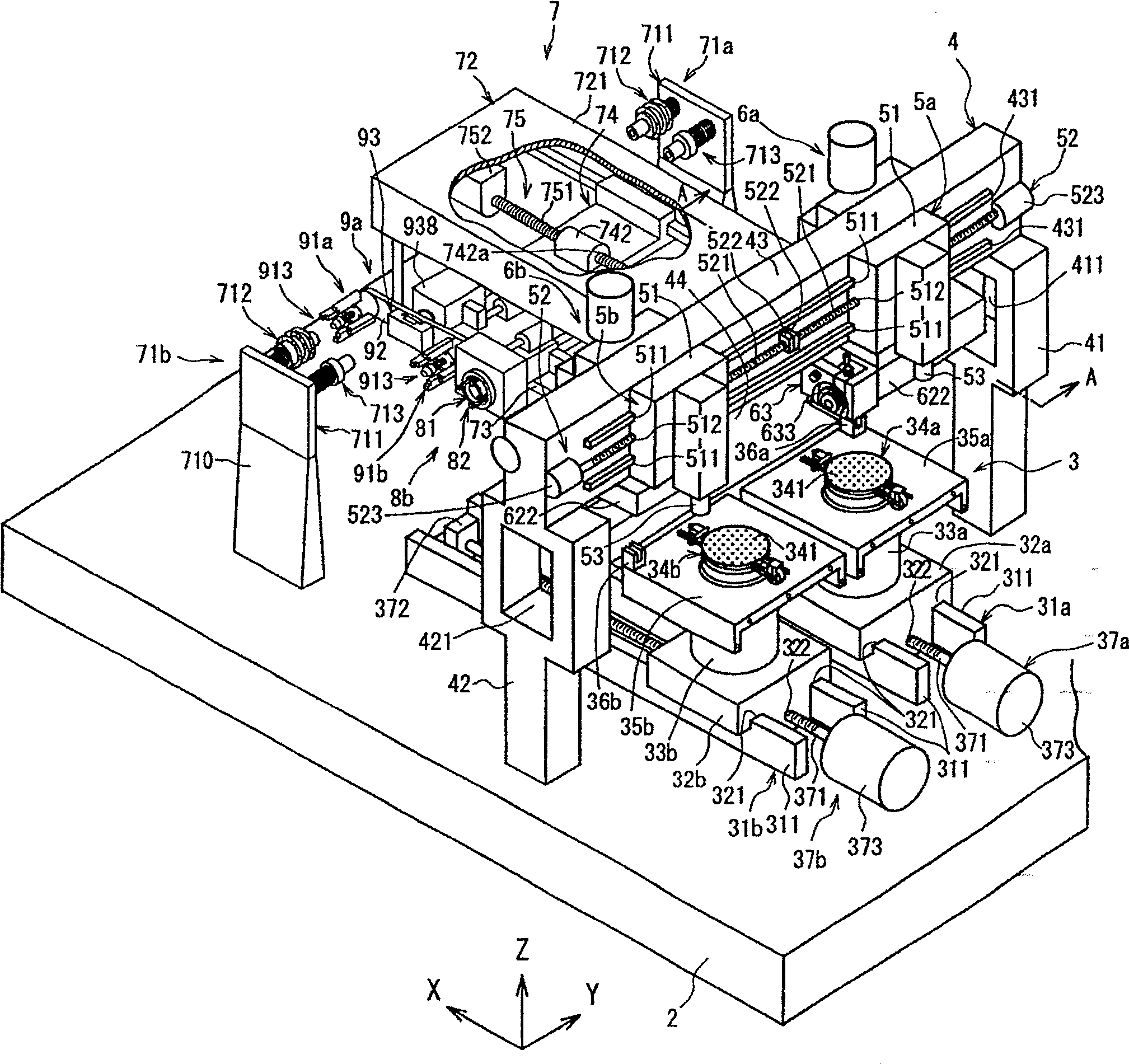
[0033] exist figure 1 , shows a perspective view of main parts of a cutting device equipped with a cutting tip replacement device according to the present invention.

[0034] figure 1 The cutting device shown has a stationary abutment 2 . On this stationary base 2, a clamping table mechanism 3 for holding a workpiece and moving it in the cutting feeding direction indicated by an arrow X is arranged.

[0035] The clamping table mechanism 3 in the illustrated embodiment has a first guide rail 31 a and a second guide rail 31 b arranged on the upper surface of the stationary base 2 . The first guide rail 31a and the second guide rail 31b are constituted by a pair of rail members 311, 311, respectively, and extend in parallel to each other along the cutting feed direction indicated by the arrow X in th...


PUM


Abstract

PROBLEM TO BE SOLVED: To provide a cutting blade exchanging device which can positively align the axis of a cutting blade gripped by a blade gripping means of a blade attachment / detachment means with an axis of a rotating spindle. SOLUTION: The cutting blade exchanging device functions to exchange cutting blades. Each of the cutting blade attachment / detachment mechanisms 9a, 9b is formed of: the cutting blade gripping means 91a, 91b for gripping the periphery of a hub 636 of the cutting blade 635; a support plate 92 on which the cutting blade gripping means is mounted; a support means 93 supporting the support plate 92; and a moving means 83 for reciprocatively moving the support means. Each cutting blade gripping means is formed of: a plurality of gripping members 911 arranged at circumferential intervals, for gripping the periphery of the hub 636 of the cutting blade 635; a gripping member moving means for operating the plurality of gripping members in a radial direction; and a positioning means arranged at the center of the plurality of gripping members, for engaging with an engaging recess 632a formed at the axial center in a front end surface of the rotary spindle 632. COPYRIGHT: (C)2007,JPO&INPIT

Description

technical field [0001] The present invention relates to a cutting blade replacement device equipped in a cutting device for cutting workpieces such as semiconductor wafers. Background technique [0002] For example, in a semiconductor device manufacturing process, IC, LSI Circuits such as these are divided into individual semiconductor chips by dividing each region in which the circuit is formed along planned division lines. As a dividing device for dividing a semiconductor wafer, a cutting device which is a dicing device is generally used. This cutting device has a clamping base for holding a workpiece, and a cutting mechanism including a cutting blade for cutting the workpiece held on the clamping base. [0003] The cutting blades equipped in the above-mentioned cutting devices are worn due to use, and therefore need to be replaced after a certain period of use. For this reason, there has been proposed an automatic blade changer that automatically replaces the cutting b...

Claims


Application Information

Patent Timeline
Patent Type & Authority Patents(China)
IPC IPC(8): B23Q3/157B28D5/02H01L21/78
CPCB23Q3/15513B23Q3/1554B27B5/32B28D5/029H01L21/78
Inventor 石井茂
Owner DISCO CORP
Why Eureka
Try Eureka