
Material slag collecting device

A collection device and a technology of slag, which is applied in the field of metal waste slag processing in mechanical processing, can solve the problems of high labor intensity, unsuitable collection of slag, and easy dripping of liquid, so as to facilitate centralized processing, control automation, cleverly structured effects

Pending Publication Date: 2022-01-07
中科九微科技有限公司
View PDF0 Cites 0 Cited by
  • Summary
  • Abstract
  • Description
  • Claims
  • Application Information

AI Technical Summary

Problems solved by technology

[0002] Metal cutting in mechanical processing is an important processing method in the manufacturing field. A large amount of metal waste slag will be generated during the machining process, and the metal waste slag can be recycled; the traditional collection method is that the staff will pass the slag generated by the machine tool through similar Put the tools for the material shovel into the material slag box. During this process, the labor intensity of the staff is high, and a lot of material slag contains liquid, and the liquid is easy to drip around when moving, which affects the working environment. It is not suitable for a large amount of material slag. the collection

Method used


Image

  • Material slag collecting device
  • Material slag collecting device
  • Material slag collecting device

Examples


Embodiment Construction

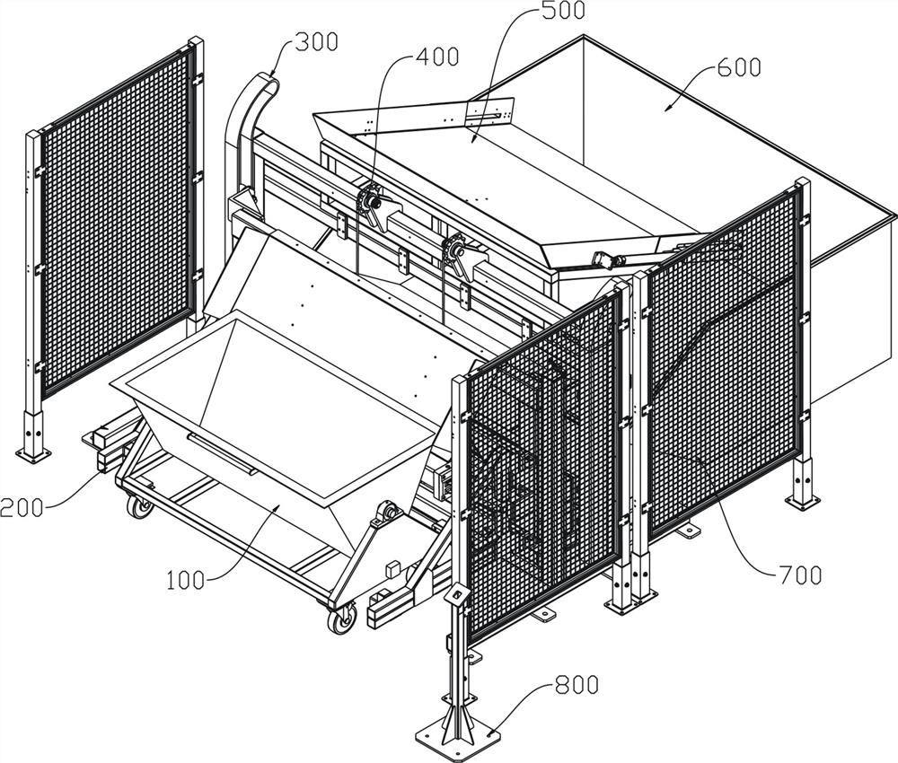
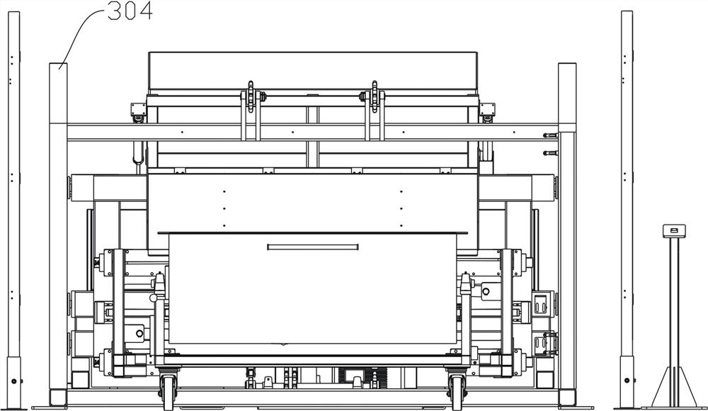
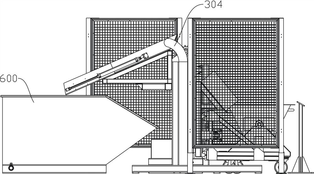
[0051] The following will be combined with Figure 1-Figure 10 The present invention is described in detail, and the technical solutions in the embodiments of the present invention are clearly and completely described. Apparently, the described embodiments are only some of the embodiments of the present invention, not all of them. Based on the embodiments of the present invention, all other embodiments obtained by persons of ordinary skill in the art without making creative efforts belong to the protection scope of the present invention.

[0052] Such as Figure 1-Figure 4 Shown, the present invention provides a kind of slag collection device here by improvement, comprises

[0053] The base frame is fixedly installed on the working base surface;

[0054] The holding mechanism 200 is installed on the feeding end of the base frame 900, and holds the trolley 100 with the slag tightly;

[0055] A lifting frame 900, one side is fixedly installed on the clasping mechanism 200, an...


PUM


Abstract

The invention discloses a material slag collecting device which comprises a base frame, an enclasping mechanism, a lifting frame, a power device and a material slag box, wherein the base frame is fixedly mounted on a working base face; the enclasping mechanism is mounted at the feeding end of the base frame and is used for enclasping a trolley filled with material slags; one side of the lifting frame is fixedly mounted on the enclasping mechanism, and the other side of the lifting frame is connected to the base frame; the power device is fixedly mounted on the base frame, is connected with the lifting frame, and drives the lifting frame on which the enclasping mechanism is mounted to move up and down and take the direction-changing motion on the base frame; and the material slag box is placed at the discharging end of the base frame. The material slag collecting device is reasonable in design, ingenious in structure and convenient to use and is used for collecting machining material slags, and is convenient for centralized treatment of the material slags; reasonable design of the enclasping mechanism can make loading and unloading of the trolley stable and reliable; reasonable design of the lifting frame and the power device can enable the enclasping mechanism to stably and reliably move up and down and take the direction-changing motion, so that the trolley can better unload materials; and the material slags discharged from the trolley are collected through the material slag box.

Description

technical field [0001] The invention relates to the field of processing metal waste slag, in particular to a slag collecting device. Background technique [0002] Metal cutting in mechanical processing is an important processing method in the manufacturing field. A large amount of metal waste slag will be generated during the machining process, and the metal waste slag can be recycled; the traditional collection method is that the staff will pass the slag generated by the machine tool through similar Put the tools for the material shovel into the material slag box. During this process, the labor intensity of the staff is high, and a lot of material slag contains liquid, and the liquid is easy to drip around when moving, which affects the working environment. It is not suitable for a large amount of material slag. collection. Contents of the invention [0003] Therefore, in order to solve the above-mentioned deficiencies, the present invention provides a kind of reasonable...

Claims


Application Information

Patent Timeline
Patent Type & Authority Applications(China)
IPC IPC(8): B65G65/23B65G65/32B65G69/00
CPCB65G65/23B65G65/32B65G69/00
Inventor 陈林康进昌
Owner 中科九微科技有限公司
Learn More