Shut-off and reversing valve

A technology for distributing valves and control panels, which is applied to valve devices, multi-way valves, transportation and packaging, etc., and can solve problems such as inability to provide independence

Inactive Publication Date: 2009-09-09
HANS GROHE GMBH & CO KG
View PDF3 Cites 0 Cited by
  • Summary
  • Abstract
  • Description
  • Claims
  • Application Information

AI Technical Summary

Problems solved by technology

Does not provide independence as the pivoting control dial of one control unit interacts with the pivoting control disc of the other unit

Method used


Image

  • Shut-off and reversing valve
  • Shut-off and reversing valve
  • Shut-off and reversing valve

Examples


Embodiment Construction

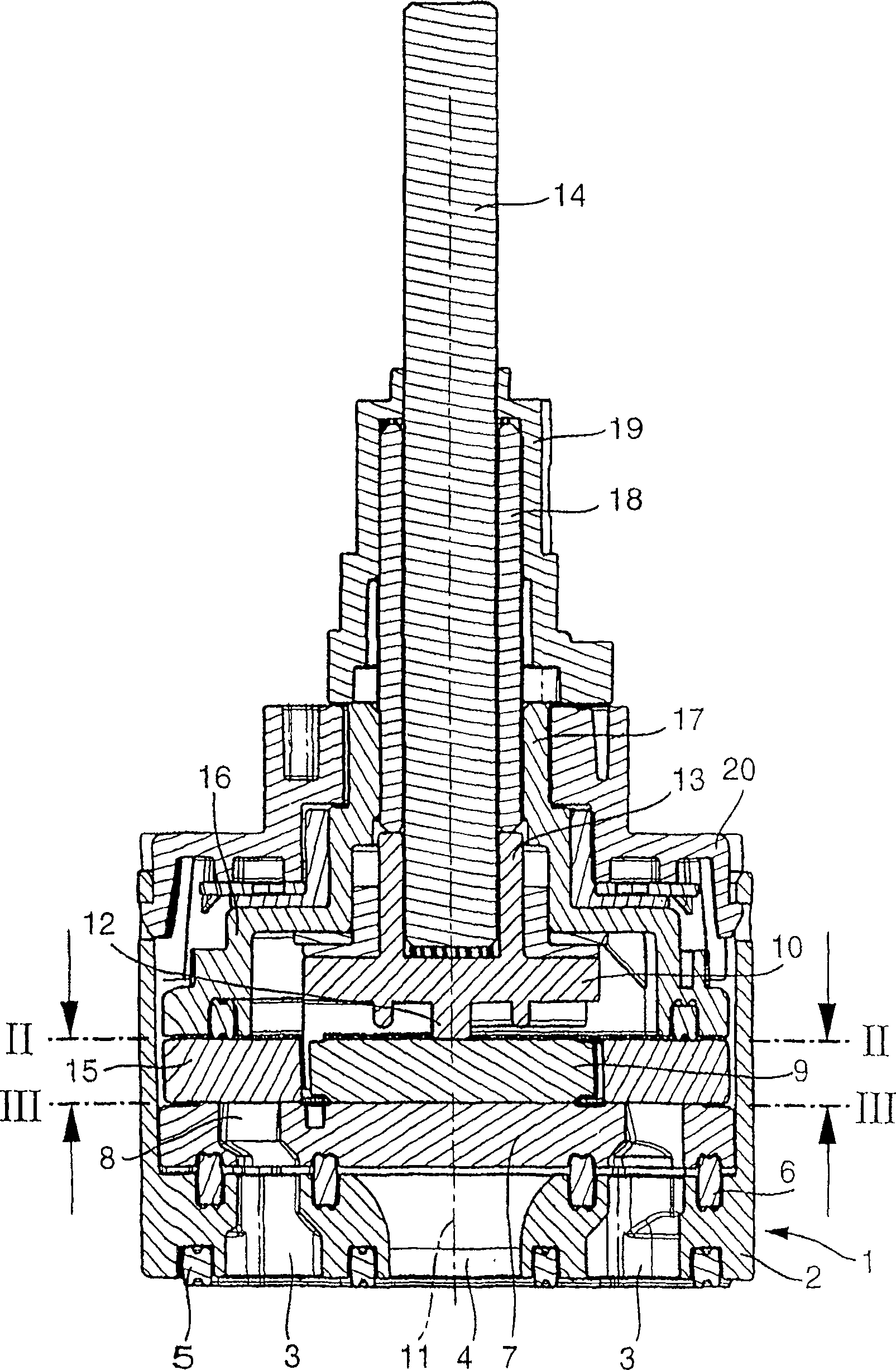
[0023] exist figure 1 The cleaning valve shown in axial section in , comprises a valve housing 1 which is closed by means of a base 2 in its bottom part. The base 2 comprises a plurality of outlet openings 3, and an inlet opening 4 in the middle. The valve housing 1 is inserted onto a fitted housing in which corresponding channels are provided. For sealing against the fitted housing, a seal 5 is provided.

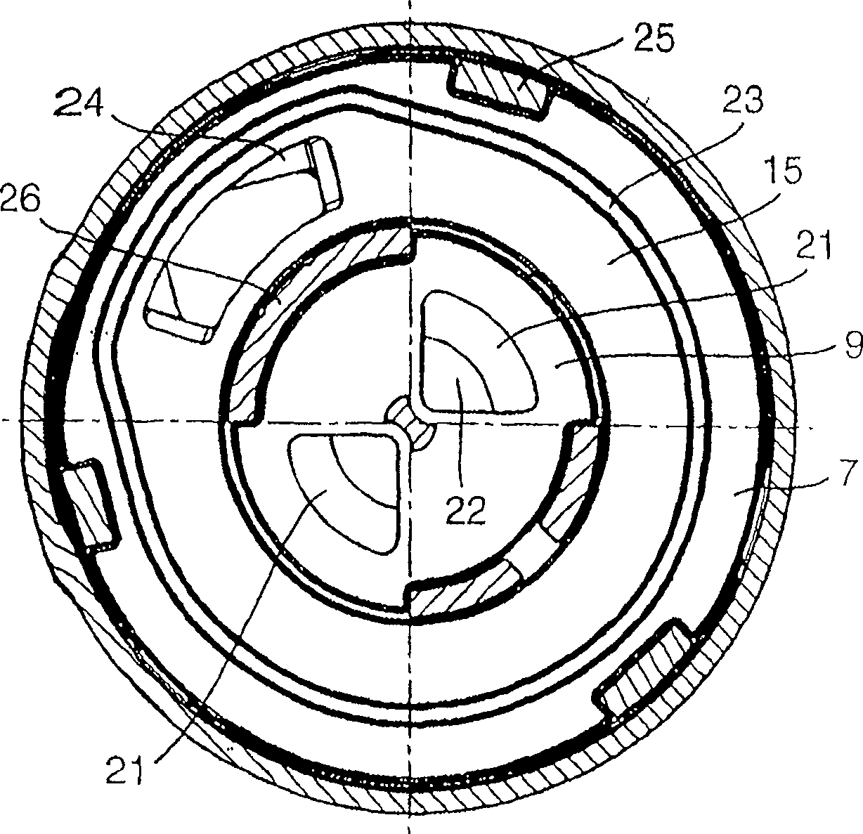
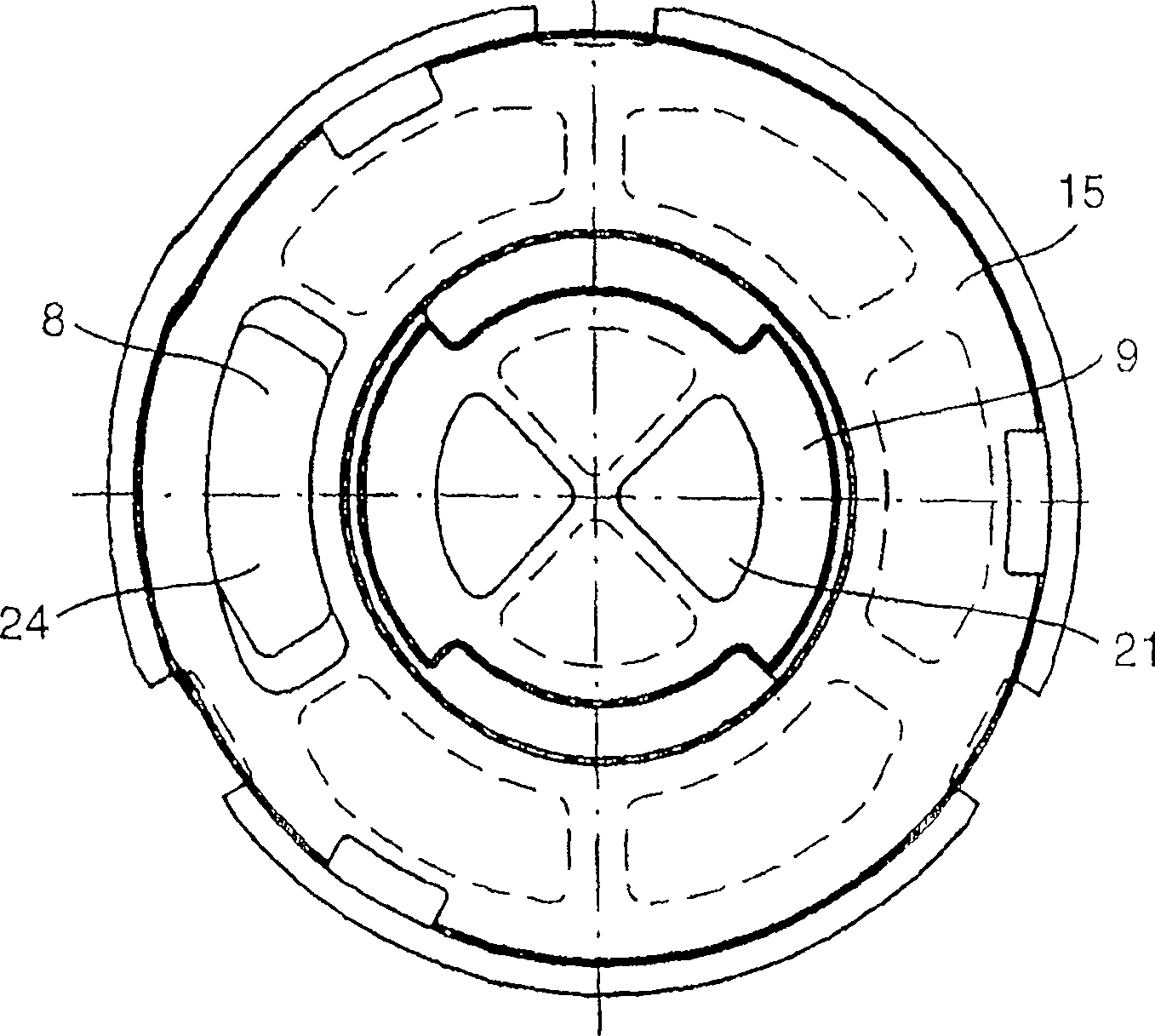
[0024] On the base 2 of the valve housing 1 , a fixed ceramic disc 7 is arranged above the seal 6 , which ceramic disc is often also referred to as a distribution disc. This distribution plate 7 has a passage opening 8 which communicates with the water outlet 3 . The distribution plate 7 is also characterized by two central cutouts, which communicate with the water inlet 4 . These middle cuts are in the figure 1 is not visible in the cross section.

[0025] Above the distribution disc 7, a first movable control disc 9 is arranged in the middle. This movable control d...


PUM


Abstract

A disc-type control valve with total volume control and distribution functions for distributing incoming water to one of several outlets (8, 3). In order that a respective movable control disk can be actuated individually to cooperate with the connected fixed distribution disk (7) for the two control devices (9, 15), the two movable control disks are aligned with each other. The pressure supports can be individually adjusted and adjusted. Two actuation parts (14, 19) are used for actuation, one of which is arranged as a sleeve around the other part.

Description

technical field [0001] The invention relates to a valve in which the possibility of closing and dispensing of water to one of several dispensing outlets are combined. Background technique [0002] Such valves are well known. Typically, there is a single actuator (or drive) with which the output and select water outlets can be actuated by the valve. Since most cleaning (or pumping) valves are made as ceramic disc valves, a problem arises in that the volume of the ceramic disc increases as the number of dispensing outlets increases. Consequently, due to the increased friction, the force required to actuate the valve increases. This applies in particular during the combined closing and dispensing activities performed in the same pair of control discs in order to reduce the overall height of the valve. [0003] A valve with which several outlets can be closed and distributed is known (see patent document US6357476). Since the pivoting control dial of one control device inter...

Claims


Application Information

Patent Timeline
Patent Type & Authority Patents(China)
IPC IPC(8): F16K11/20F16K11/074
CPCF16K11/0743Y10T137/88062Y10T137/87129Y10T137/87072F16K11/202Y10T137/86501
Inventor W·洛奇
Owner HANS GROHE GMBH & CO KG
Why Eureka
Try Eureka