Parking lock device for motor vehicle

A technology for motor vehicles, parking locks, used in transmission control, mechanical equipment, elements with teeth, etc.

Pending Publication Date: 2021-12-07
ZF FIEDRICHSHAFEN AG
View PDF2 Cites 0 Cited by
  • Summary
  • Abstract
  • Description
  • Claims
  • Application Information

AI Technical Summary

Problems solved by technology

In the case of holding the locking pawl in the disengaged state, this is particularly the case when the motor vehicle is highly dynamic and the disengagement spring is dimensioned such that a relatively small actuation force is required to engage the parking lock. may cause problems

Method used


Image

  • Parking lock device for motor vehicle
  • Parking lock device for motor vehicle
  • Parking lock device for motor vehicle

Examples


Embodiment Construction

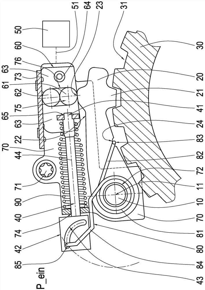
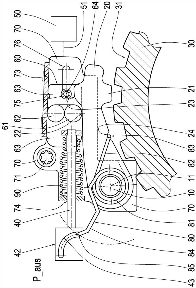
[0035] Refer below Figure 1A , Figure 1B and Figure 4 A first preferred embodiment of the parking lock device for a motor vehicle according to the invention is described in detail. Figure 1A The parking lock is shown in the "parking lock engaged" switching position, which is identified with the reference symbol P_ein. and Figure 1B The parking lock is shown in the "parking lock disengaged" switching position, which is identified with the reference symbol P_aus. At last, Figure 4 The force / distance diagram shows the force curve for the spring element used in the first embodiment example, by means of which the parking lock device is held in the disengaged state.

[0036] exist Figure 1A and Figure 1B The parking lock device shown in is structurally based on the parking lock device known from DE 10 2019 101 467 A1 and comprises a locking pawl mounted pivotably on the pawl bolt 10 20, the pawl tooth 21 of the locking pawl is locked into or disengaged from the tooth ga...


PUM


Abstract

The invention relates to a parking lock device for a motor vehicle. The device has a pivotably mounted locking pawl (20) which engages into or disengages from a parking lock gear (30) acting on a wheel of the motor vehicle; an axially displaceable locking element (60) which is clamped between the locking pawl (20) and the guide plate (73) in the engaged state of the parking lock device; an actuating device (50) acting axially on the locking element; a guide rod (40) connected or operatively connected with the locking element (60) and axially displaced; and a spring element (80) which preforces the locking pawl (20) in the disengagement direction. The first free end of the spring element is directly supported on the supporting section of the locking pawl, and the second free end of the spring element is directly supported on the supporting contour of the connecting rod. The geometry of the support contour is embodied such that the preload of the spring element is not reduced when the parking lock is disengaged.

Description

technical field [0001] The invention relates to a parking lock device for a motor vehicle, said parking lock device comprising a locking pawl pivotably supported on a pawl bolt, said locking pawl engaging Locked into or disengaged from a parking lock gear acting on a wheel of the motor vehicle; a locking element axially displaceable when the parking locking device is engaged and disengaged, the locking element In the engaged state of the parking lock device, it is sandwiched between the locking pawl and the guide plate fixed to the housing to prevent the locking pawl from dislodging from the teeth of the parking lock gear. squeezed out of the gap; an actuating device acting on the locking element in an axial direction to disengage the parking lock; a guide rod connected or operatively connected to the locking element, the the guide rod is axially displaced when the parking lock is engaged and disengaged; and a spring element that acts on the locking pawl in the disengagement ...

Claims


Application Information

Patent Timeline
Patent Type & Authority Applications(China)
IPC IPC(8): F16H63/38F16H63/34
CPCF16H63/38F16H63/34F16H63/3433F16H63/36
Inventor M·列斯特
Owner ZF FIEDRICHSHAFEN AG
Why Eureka
Try Eureka