Teeth spray-rinsing device having two detachably connectable housings

A spray washer and tooth cleaning technology, which is applied in the direction of cleaning teeth, spraying devices, distribution devices, etc., can solve the problems of troublesome insertion of the riser, easy damage of the riser, and lifting of the handle

Inactive Publication Date: 2009-09-16
GIMELLI LAB
View PDF6 Cites 0 Cited by
  • Summary
  • Abstract
  • Description
  • Claims
  • Application Information

AI Technical Summary

Problems solved by technology

On the one hand, a relatively thick product is produced by the parallel arrangement of the pump housing and the water reservoir, which is heavy to handle
On the other hand the riser is susceptible to damage when the water reservoir is replaced, so the riser has to be inserted into the water reservoir with relative trouble

Method used


Image

  • Teeth spray-rinsing device having two detachably connectable housings
  • Teeth spray-rinsing device having two detachably connectable housings
  • Teeth spray-rinsing device having two detachably connectable housings

Examples


Embodiment Construction

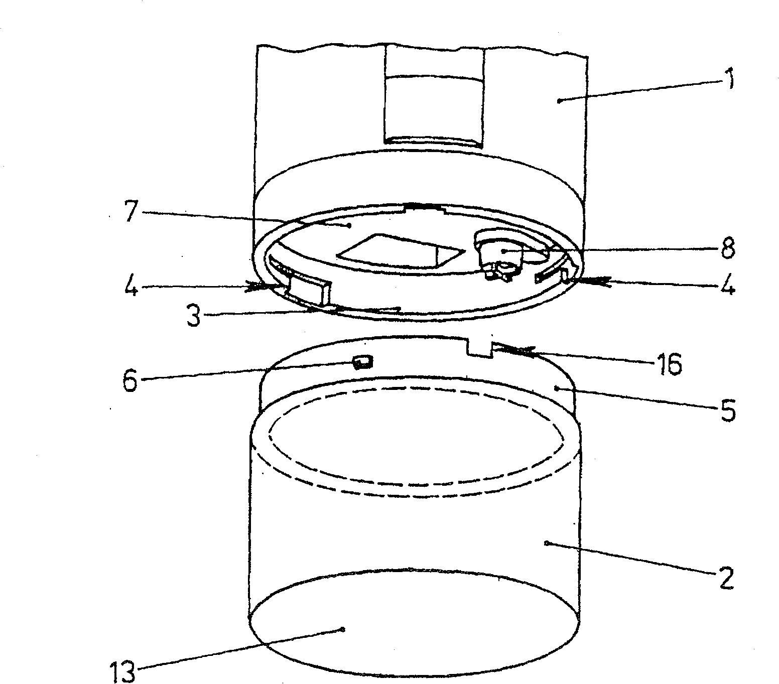
[0022] First according to figure 1 Be explained.

[0023] The lower part of the cylindrical pump housing 1 is shown in the upper part of the figure. There is an electric pump and a battery or a rechargeable battery for driving the motor in the pump housing 1, but no further description is given here. The lower part of the figure is a water reservoir 2, which is also cylindrical and has the same outer diameter as the pump casing. Therefore, the two casings are smoothly integrated with each other and form a straight cylindrical clean tooth sprayer casing. .

[0024] In order to connect the pump housing 1 and the water reservoir 2, the pump housing 1 has a surrounding partition 3 with three crescent plates 4 for bayonet connection inside.

[0025] The upper edge 5 of the water reservoir 2 presents an inward stepped shape, and therefore can be inserted into the opening formed by the partition 3. A plurality of Kulissenzapf 6 is located on the outside of the edge 5, which is inserted ...


PUM


Abstract

Microswitch for application in electrical switches or relays in which a movable massive element is moved using a collected charge stored in a capacitor (1). Independent claims are included for an apparatus for moving a tool and for moving a motor in the area of microtechnology and nanotechnology, for moving tractors, submarines, airplanes.

Description

Technical field [0001] The present invention relates to a tooth cleaning sprayer, which has two mutually separable shells, wherein the first shell is a pump shell with at least one pump inside and a drain port at the upper end, wherein the second shell constitutes a pump shell A water reservoir, and wherein the pump is connected to a riser pipe located above the bottom of the water reservoir. Background technique [0002] Such a tooth cleaning sprayer is described in, for example, German Patent DE19525718: a slender pump housing has a drain at the upper end, a pump under the drain in the pump housing, and a motor driving the pump under the pump. There is a battery at the bottom of the pump housing to provide power to the pump. Next to the pump housing is a second housing formed by a water reservoir, which actually extends the total length of the pump housing and is detachably connected to the pump housing. A riser pipe extends from the lower side of the protruding part in the upp...

Claims


Application Information

Patent Timeline
Patent Type & Authority Patents(China)
IPC IPC(8): A61C17/00B67D7/78A61C17/02B05B15/00B05B15/30
CPCB05B15/005A61C17/02B05B9/0861B05B15/30
Inventor 阿尔弗雷德·舒茨
Owner GIMELLI LAB
Why Eureka
Try Eureka