Friction clutch

A clutch and friction technology, applied in the field of light

Inactive Publication Date: 2009-09-16
SCHAEFFLER TECH AG & CO KG
View PDF13 Cites 2 Cited by
  • Summary
  • Abstract
  • Description
  • Claims
  • Application Information

AI Technical Summary

Problems solved by technology

In foot-operated clutches, excessive force fluctuations during clutch operation also cause disturbances

Method used


Image

  • Friction clutch
  • Friction clutch
  • Friction clutch

Examples


Embodiment Construction

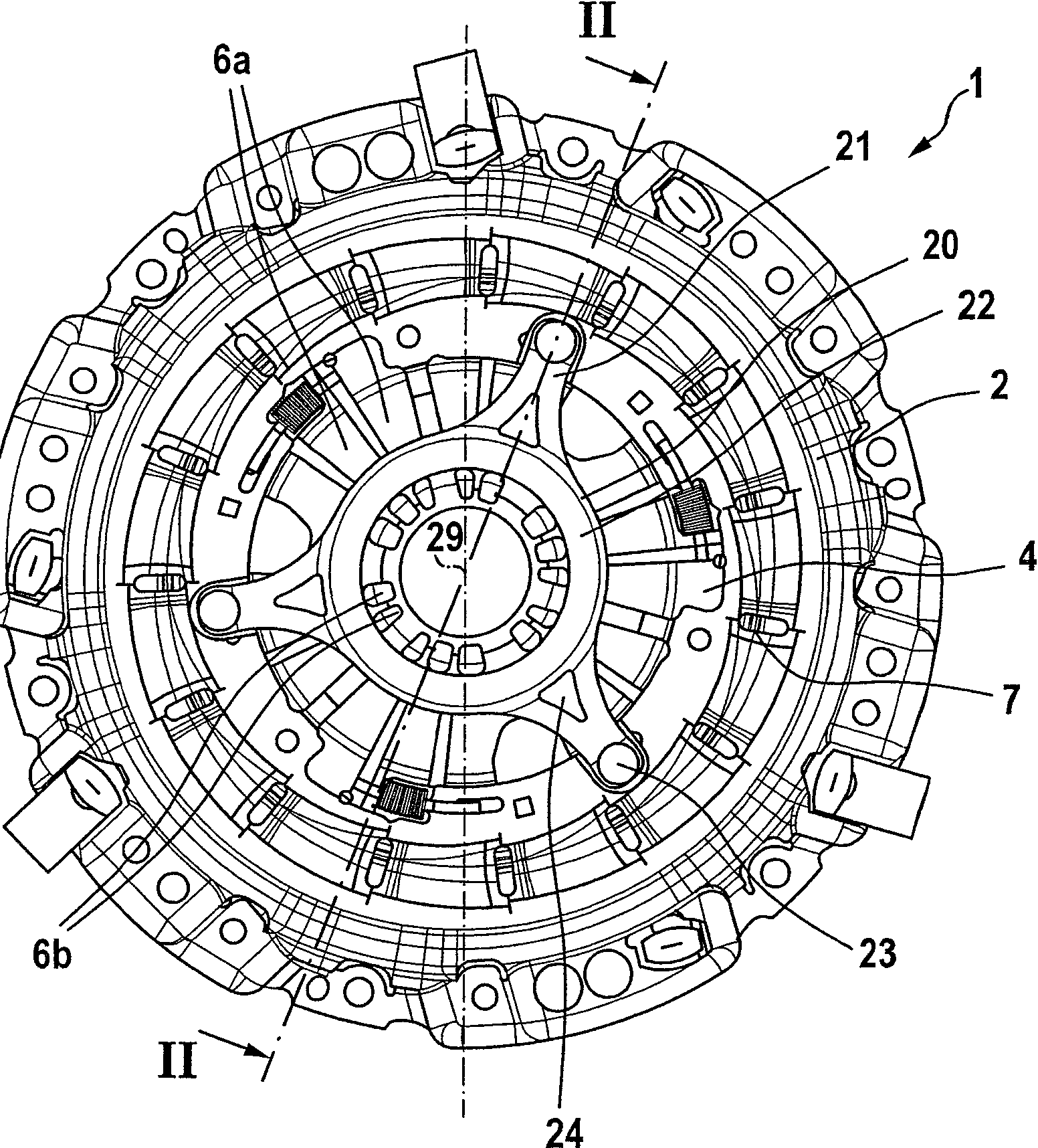
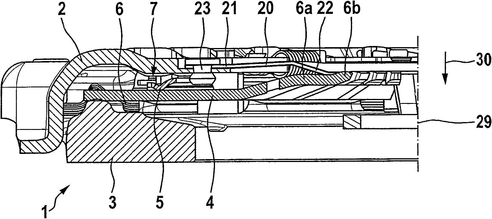
[0022] figure 1 and figure 2The friction clutch 1 shown in has the same characteristics as described in DE 10025850A1 in terms of the configuration of the compression disk spring 4 and its support on the clutch housing 2 and in the transmission connection between the pressure plate 3 and the cover 2 A structure similar to that described above. Furthermore, the friction clutch 1 has a self-acting or automatic compensating device 7 which is able to compensate for wear occurring at least on the friction linings of the clutch disc. In the embodiment shown here, the compensating device acts axially between the clutch housing 2 (cover) and the disk spring 4, so that the axial compensation adjustment of the disk spring 4 can compensate the wear and tear. In addition, reference can be made to the above-mentioned DE 10025850A1, DE 4322677A1, DE 19524827A1 and DE 19855583A1 regarding the function and configuration possibilities of this compensating device 7, the content of which is ...


PUM


Abstract

The friction clutch has an axially displaceable pressure plate which via a disc spring is acted upon by a clutch plate installed on a flywheel. At least one additional spring element influences the force characteristic required for the operating of the clutch over a part of the clutch operating action. The additional spring element is formed by at least one membrane-like spring (120) supported on the housing on one side and on the disc spring on the other side in such a way that during a conicity change of the disc spring occurring during clutch operation the membrane spring experiences a material deformation both in the axial and radial directions.

Description

technical field [0001] The invention relates to a friction clutch, in particular a friction clutch for motor vehicles, which has a pressure plate which is non-rotatable relative to the housing but which can move to a limited extent in the axial direction, the pressure plate is supported by a pivotable The disc spring on the housing can be loaded in the direction towards a clutch plate arranged between the flywheel and the pressure plate in the state when the friction clutch is assembled on the flywheel, wherein at least one further spring part is provided, During actuation of the friction clutch, the spring element influences the force profile required for actuating the friction clutch at least over a partial region of the actuation process. The superposition of the force curves of two spring elements is known, for example, from DE 4013186 C2 and DE 3991022 C2. In this case, the superimposition of the second spring part arranged in parallel with the pressure disc spring serve...

Claims


Application Information

Patent Timeline
Patent Type & Authority Patents(China)
IPC IPC(8): F16D13/58F16D13/71
CPCF16D13/583
Inventor 汤姆·利伯曼卡尔-路德维希·基米希
Owner SCHAEFFLER TECH AG & CO KG
Why Eureka
Try Eureka