Supercharge Your Innovation With Domain-Expert AI Agents!

Piezoelectric hydraulic pump

A hydraulic pump and piezoelectric technology, applied in the field of hydraulic pumps, can solve the problems of difficult manufacturing, high cost, and small power-to-mass ratio, and achieve the effects of no electromagnetic interference, simple structure, and low energy consumption

Active Publication Date: 2009-10-07
HARBIN INST OF TECH
View PDF5 Cites 0 Cited by
  • Summary
  • Abstract
  • Description
  • Claims
  • Application Information

AI Technical Summary

Problems solved by technology

[0003] In order to solve the problem that most existing piezoelectric pumps developed by piezoelectric materials have large structural dimensions, small power-to-mass ratio, and very small output pressure, they are far from being able to drive actuators to generate motion. Traditional hydraulic pumps have very complicated structures and are difficult to manufacture. To solve the problem of large size and high cost, a piezoelectric hydraulic pump is provided. The specific technical solution to solve the above problems is as follows:

Method used


Image

  • Piezoelectric hydraulic pump
  • Piezoelectric hydraulic pump
  • Piezoelectric hydraulic pump

Examples


specific Embodiment approach 1

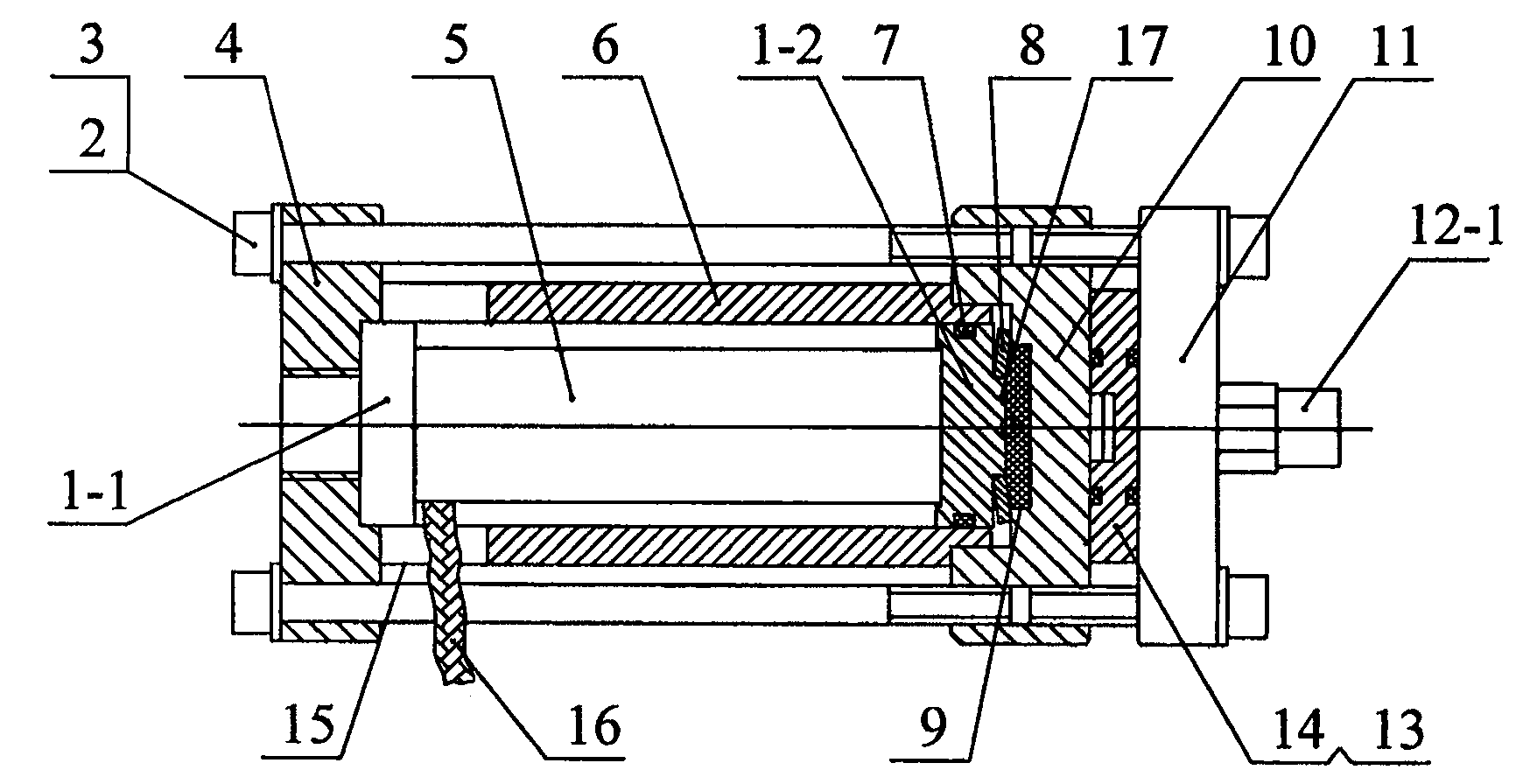
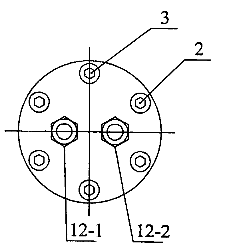
[0007] Specific implementation mode one: combine figure 1 The present embodiment will be described. This embodiment consists of a first guide block 1-1, a second guide block 1-2, a hexagon socket head cap screw 2, a left end cover 4, a piezoelectric actuator 5, a cylinder body 6, an O-ring 7, a disc spring 8, Right end cover 10, cover plate 11-, oil inlet pipe joint 12-1, oil outlet pipe joint 12-2, oil inlet valve 13 and oil outlet valve 14, the first guide block 1-1 is set at the left end of the cylinder body 6 cavity 1. The second guide block 1-2 is located at the right end in the cylinder block 6 cavity, and the right end surface of the second guide block 1-2 is provided with a boss 17, and the disk spring 8 is fixed on the boss 17, and the second guide block The outer ring of 1-2 is provided with an O-ring 7, the piezoelectric actuator 5 is located in the cavity of the cylinder body 6, the left end surface of the first guide block 1-1 is embedded in the right end surface...

specific Embodiment approach 2

[0008] Embodiment 2: In this embodiment, the left end of the cylinder body 6 is provided with a cable groove 15, and the piezoelectric cable 16 is connected to a power source.

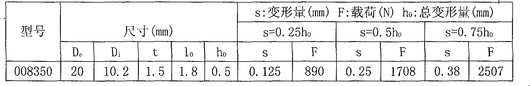
[0009] In the present invention, disc springs 8 are arranged on the boss 17 of the second guide block 1-2, and a sealed cavity 9 is formed on the right end surface of the second guide block 1-2 and the middle recess at the left end of the right end cover 10. When the system pressure exceeds Working pressure, liquid will overflow from the contact surface of disc spring 8 and right end cover 10, plays the effect of safety valve. Because the spring strain has a good linear relationship with the load, it can also improve the dynamic characteristics of the system, so that the piezoelectric actuator 5 can obtain a larger amplitude and increase the output flow of the piezoelectric hydraulic pump.

[0010] working principle:

[0011] Using the inverse piezoelectric effect of piezoelectric materials, when an a...


PUM


Abstract

The invention diskloses a piezoelectric hydraulic pump and relates to a hydraulic pump, solves the problems of low output pressure, complex structure and difficult manufacture of the existing pump. A guide block (1-1) of the pump is arranged on the left end inside the cavity of a cylinder body (6); a guide block (1-2) is arranged on the right end inside the cavity of the cylinder body (6); a boss (17) is arranged on the right face of the guide block (1-2); the boss (17) is provided with a saucer washer (8); an O-shaped circle (7) is arranged on an external ring of the guide block (1-2); a piezoelectric actuator (5) is arranged inside the cylinder body (6); the left face of the guide block (1-1) is embedded on the right face of a left cover cap (4); a sealing cavity (9) is arranged between the right face of the guide block (1-2) and a right cover cap (10); the left cover cap (4) is fixedly connected with the right cover cap (10) via a hexagon socket screw (2); an oil inlet valve (13) and an oil outlet valve (14) are arranged between the left face of the right cover cap (10) and a cover plate (11). The piezoelectric hydraulic pump has the advantages of simple structure, small volume, light weight, low energy consumption, noiselessness and no electromagnetic interference.

Description

technical field [0001] The invention relates to a hydraulic pump. Background technique [0002] The minimum size of electrical components depends on the maximum effective magnetic flux density, and the maximum effective magnetic flux density is limited by the magnetic saturation of the magnetic material. The magnetic flux density of the magnetic material reaches a certain saturation value with the increase of the applied magnetic field strength, so only The size of the magnetic material can be increased to increase the power. Therefore, the structural size of electrical components is large and the power-to-mass ratio is small; in the application field of driving micro-machines, traditional hydraulic pumps have high manufacturing precision, complex structures, and high manufacturing difficulty and cost. At present, the output pressure of most piezoelectric pumps developed by piezoelectric materials is very small, which is far from being able to drive actuators. Contents of...

Claims


Application Information

Patent Timeline
IPC IPC(8): F04B17/03F04B9/02H01L41/08
Inventor 冷劲松刘彦菊张波
Owner HARBIN INST OF TECH
Features
  • R&D
  • Intellectual Property
  • Life Sciences
  • Materials
  • Tech Scout
  • Unparalleled Data Quality
  • Higher Quality Content
  • 60% Fewer Hallucinations
Learn More