Supercharge Your Innovation With Domain-Expert AI Agents!

A Micropump Device Driven by Photostrictive Material

A light-driven, micro-pump technology, applied to pumps with flexible working elements, pumps, machines/engines, etc., can solve problems affecting precise control, weak driving ability, small electrostatic driving force, etc., to avoid electromagnetic noise interference, Simple and compact structure, easy to output flow effect

Active Publication Date: 2016-04-20
NANJING UNIV OF SCI & TECH
View PDF6 Cites 0 Cited by
  • Summary
  • Abstract
  • Description
  • Claims
  • Application Information

AI Technical Summary

Problems solved by technology

Piezoelectric driving displacement is small, requires high driving voltage, and is susceptible to electromagnetic interference; electrostatic driving force is small, displacement is also small and requires high voltage; electromagnetic driving is limited by the size of the electromagnetic coil, and it is not easy to miniaturize the structure; bimetal Actuation uses thermal effects to drive two metals with different expansion coefficients to achieve actuation, but the actuation ability is weak, the efficiency is relatively low, and the working frequency is very low; shape memory alloys are driven by temperature changes, so the frequency is low and is greatly affected by temperature and poor controllability
[0003] In summary, the above methods have their own shortcomings, which affect the precise control of the flow rate of the micropump or limit the miniaturization of the micropump structure. In contrast, the light-driven micropump based on photostrictive materials embodies Its huge advantages, optical drive can realize remote non-contact control, no noise, no pollution and no electromagnetic interference, simple and compact structure, easy to realize the miniaturization of the structure, providing a broad application prospect for micropumps
But there is no relevant description in the prior art

Method used


Image

  • A Micropump Device Driven by Photostrictive Material
  • A Micropump Device Driven by Photostrictive Material

Examples


Embodiment Construction

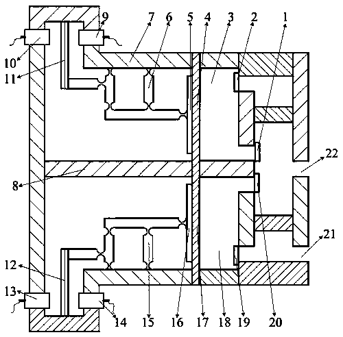
[0016] combine figure 1 , a light-driven micro-pump device of the present invention includes an upper pump, a lower pump, an upper pump driving amplifying mechanism, a lower pump driving amplifying mechanism, a pump body 7, a water outlet 22 and a water inlet 21, and the middle of the pump body 7 is provided with There is a pump body center plane 8, the pump body center plane 8 is located on the central axis of the pump body 7, the upper pump is located above the pump body center plane 8, the lower pump is located below the pump body center plane 8, and the upper pump is driven to enlarge The mechanism is connected with the upper pump membrane cover 5 of the upper pump, and is used to drive the upper pump to realize pumping water. The lower pump driving amplifying mechanism is connected with the lower pump membrane cover 16 of the lower pump, and is used to drive the lower pump to realize pumping water, wherein the upper pump and The lower pump has the same structure and is sy...


PUM


Abstract

The invention discloses a micropump device driven by photostrictive materials. The micropump device comprises pump diaphragms, ultraviolet sources, PLZT bimorphs, displacement amplification and horizontal moving mechanisms, pump cavities, water inlet valves, water outlet valves and the like. Pump drive amplifying mechanisms are connected with pumps through flexible hinges. The pumps and the pump drive amplifying mechanisms are symmetrically arranged. The water outlet valves of the two pump cavities are communicated with each other, and the water inlet valves are communicated with each other, namely the two pump cavities are connected in parallel. When the two sides of each PLZT bimorph are irradiated, the PLZT bimorphs bend leftwards or rightwards, and bending displacement is amplified and transferred through the displacement amplification and horizontal moving mechanisms to cause sinking or protruding of the pump diaphragms, so that the volumes of the pump cavities change, water is pumped, and the pump drive amplifying mechanisms are asynchronously controlled to achieve stability of liquid flow. By the adoption of the photic-driving micropump device, light-control non-contact control can be achieved, and electromagnetic interference can be avoided; the PLZT bimorphs directly convert optical energy into mechanical energy, the transmission error of intermediate machines is eliminated, the structure is simple and compact, and accurate control over liquid flow is facilitated.

Description

technical field [0001] The invention relates to a micro-pump device, in particular to a micro-pump device driven by photostrictive materials. Background technique [0002] Microfluidic system is an important branch of microelectromechanical system, which has broad application prospects in the fields of medicine, chemistry, biological engineering, aerospace and automobile engine fuel supply. The micropump is the core component of the microfluidic system, and it is the power element that realizes the supply of microflow, and can transmit the microflow accurately. At present, the volume change of the pump cavity is driven by the reciprocating change of the driving membrane, so as to realize the function of the pump. The driving methods of the driving membrane include piezoelectric, electrostatic, electromagnetic, bimetallic actuation, and shape memory alloy actuation. Piezoelectric drive has a small displacement, requires high driving voltage, and is susceptible to electromag...

Claims


Application Information

Patent Timeline
Patent Type & Authority Patents(China)
IPC IPC(8): F04B19/00F04B43/02
Inventor 王新杰黄家瀚王炅陆静黄学功
Owner NANJING UNIV OF SCI & TECH
Features
  • R&D
  • Intellectual Property
  • Life Sciences
  • Materials
  • Tech Scout
  • Unparalleled Data Quality
  • Higher Quality Content
  • 60% Fewer Hallucinations
Learn More