Radio communication device
A kind of equipment and antenna technology, which is applied in the field of radio communication equipment, can solve the problems of deterioration of antenna characteristics and small installation space of antenna devices, and achieve the effect of expanding frequency bandwidth, reducing the deterioration of antenna characteristics, and stabilizing installation
- Summary
- Abstract
- Description
- Claims
- Application Information
AI Technical Summary
Problems solved by technology
Method used
Image

Examples
no. 1 approach
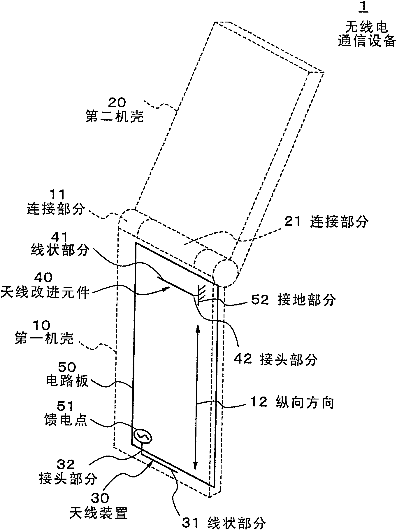
[0030] These figures are used to explain the first embodiment of the present invention. figure 1 is a perspective view schematically showing the configuration of the radio communication device according to the first embodiment of the present invention.
[0031] refer to figure 1 , the radio communication device 1 is a radio communication device including a cellular phone or the like having a foldable casing. The radio communication device 1 has a first housing 10 , a second housing 20 , an antenna arrangement 30 , an antenna improvement element 40 and a printed circuit board 50 .
[0032] The first case 10 is a case on which at least the antenna device 30 , the antenna improving element 40 and the circuit board 50 are mounted, and has a connection portion 11 . For example, the first cabinet 10 may be a cabinet serving as an operation side having a microphone and a keyboard. The connection portion 11 is located near a central portion in the longitudinal direction 12 of the c...
no. 2 approach
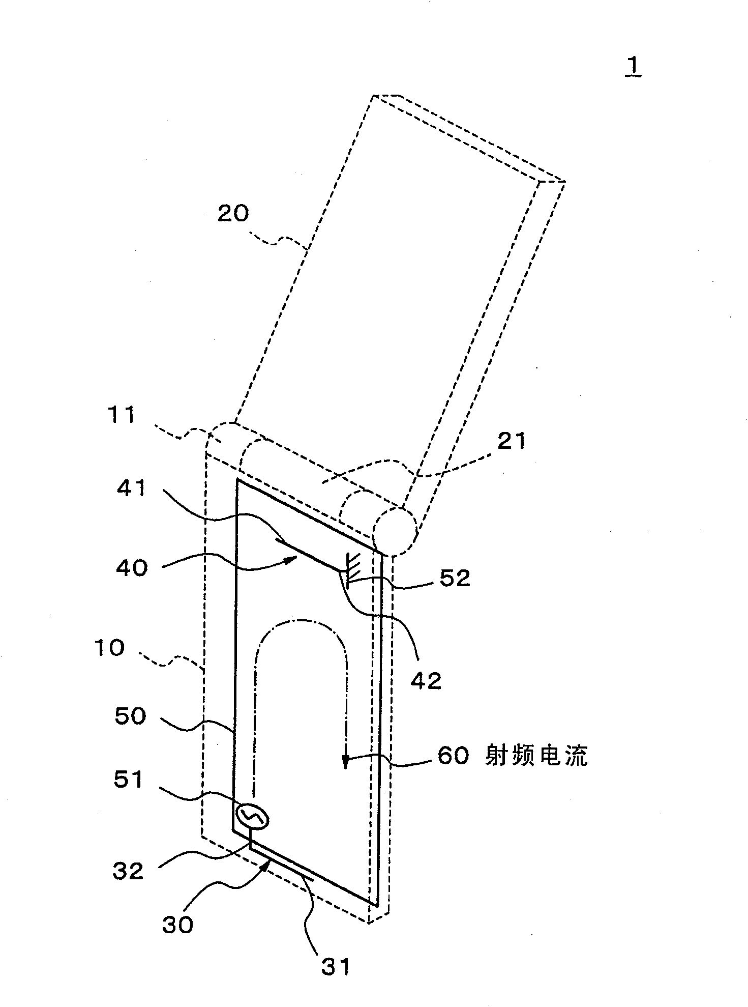
[0046] Next, the diagrams shown are used to explain the second embodiment of the present invention. Image 6 is a perspective view schematically showing the configuration of a radio communication device according to a second embodiment of the present invention. In the second embodiment, the linear portion 41 of the antenna improving element 40 is composed of a metal plate. The antenna improvement element is formed in an L shape, including a line portion 41 and a joint portion 42 . The metal plate may be a conductive plate comprising carbon fiber reinforced plastic (CFRP). Other components are similar to those of the first embodiment. The linear portion 41 is formed using a conductive plate, thereby increasing the frequency bandwidth.
no. 3 approach
[0048] Next, the diagrams shown are used to explain the third embodiment of the present invention. Figure 7 is a perspective view schematically showing the configuration of a radio communication device according to a third embodiment of the present invention. According to the third embodiment, the linear portion 41 of the antenna improving element 40 is formed as a metal wire (or metal plate) having an L shape twisted into a zigzag shape. The metal wire (or metal plate) may be a conductive wire (or conductive plate) including carbon fiber reinforced plastic (CFRP). Other components are similar to those of the first embodiment. Since the linear portion 41 is formed in a zigzag shape, the linear portion 41 can be made smaller. Furthermore, in just the same installation space, the entire length of the linear portion 41 is longer when the zigzag shape is used than when it is formed as a straight line. Therefore, the device can handle lower frequencies.
PUM
 Abstract
Description
Claims
Application Information
 - Generate Ideas
- Intellectual Property
- Life Sciences
- Materials
- Tech Scout
- Unparalleled Data Quality
- Higher Quality Content
- 60% Fewer Hallucinations
Browse by: Latest US Patents, China's latest patents, Technical Efficacy Thesaurus, Application Domain, Technology Topic, Popular Technical Reports.
© 2025 PatSnap. All rights reserved.Legal|Privacy policy|Modern Slavery Act Transparency Statement|Sitemap|About US| Contact US: help@patsnap.com