Method and apparatus for making interrupted spinning process to recovering production

A drafting device, technology of conveying process, applied in the field of production and device for resuming interrupted spinning process

Inactive Publication Date: 2009-10-28
MASCHINENFABRIK RIETER AG
View PDF6 Cites 0 Cited by
  • Summary
  • Abstract
  • Description
  • Claims
  • Application Information

AI Technical Summary

Problems solved by technology

Both speeds have disadvantages in terms of reproducibility

Method used


Image

  • Method and apparatus for making interrupted spinning process to recovering production
  • Method and apparatus for making interrupted spinning process to recovering production
  • Method and apparatus for making interrupted spinning process to recovering production

Examples


Embodiment Construction

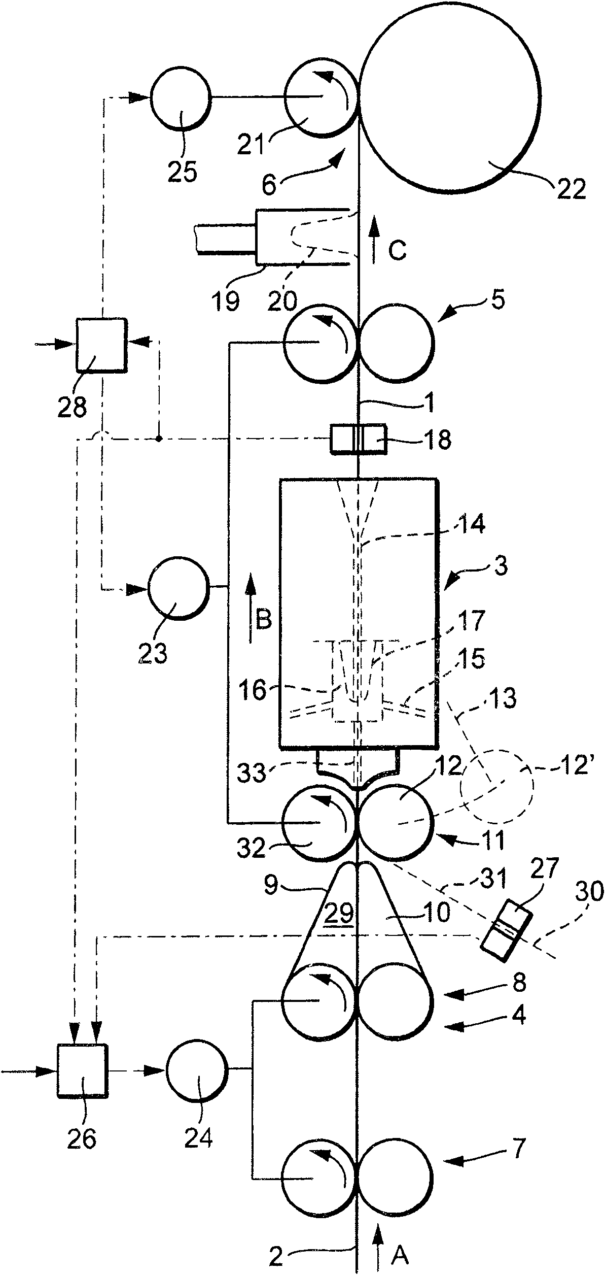
[0020] according to figure 1 The spinning equipment is used to spin a staple fiber 2 into a yarn 1. The main components of the spinning plant include an air injection device 3 - which can be designed, for example, according to the aforementioned EP 12 19 737 A1, and a drafting device 4 preferably designed as a three-roller drafting unit. , a pair of guide rollers 5 and a winding device 6.

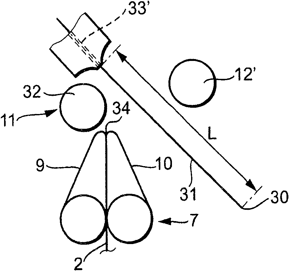
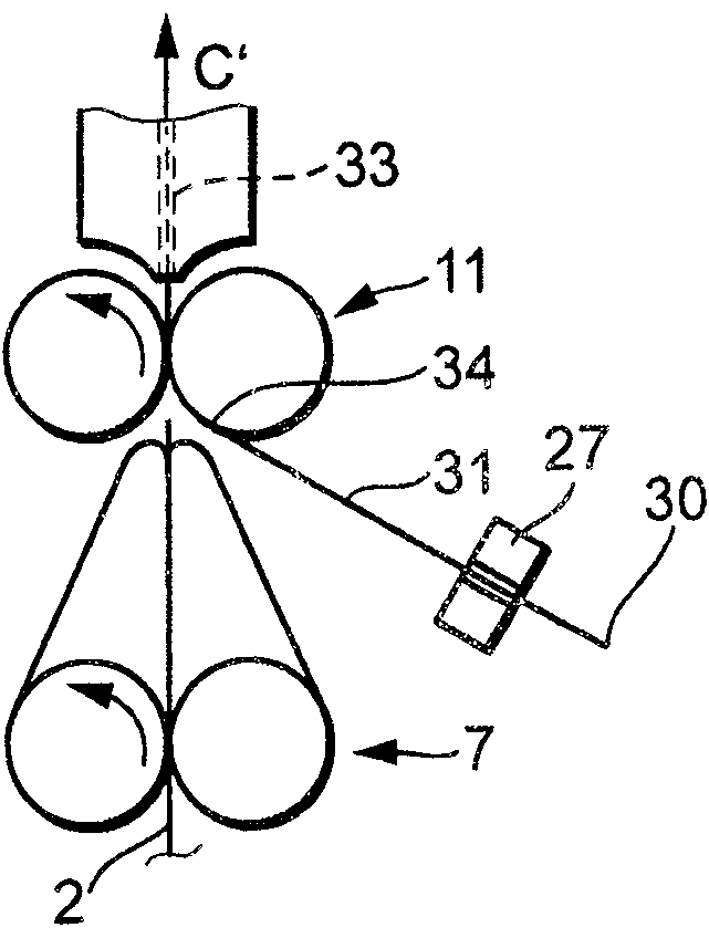
[0021] The illustrated drafting device 4 comprises a pair of feed rollers 7-a staple fiber 2 to be drawn is fed to the roller pair according to the feed direction A, and further comprises a pair of apron rollers 8-the apron rollers The pair consists of guide aprons 9 and 10 in a known manner and comprises a pair of output rollers 11 at which the drafting zone 29 of the drafting device 4 ends. In the drafting unit 4, the staple fibers 2 are drawn to the desired fineness in a known manner.

[0022] The delivery roller pair 11 consists of a driven bottom roller 32 and a pressure roller 12 a...


PUM


Abstract

In a process to splice a broken thread in an air jet textile spinning assembly, the thread free end with loose filaments is positioned close to a pair of feed rollers. The thread is then advanced followed by a feed of staple sliver. During the splicing process, the speed of advance of each thread is determined by the position of the broken thread, both being at constant and reduced speeds. - During the splicing procedure both the thread and sliver are transported by the feed rollers. The position of the thread end is detected by a sensor that is linked to the sliver feed drive. The leading section of the sliver is discarded as waste between the feed roller and air jet before the splicing operation. After release of the waste normal spinning process resumes. Also claimed as a commensurate assembly.

Description

technical field [0001] The invention relates to a method for resuming an interrupted spinning process on a spinning plant having an air injection device and a drafting device in which an already spun yarn is prepared One head end of the drafting device is positioned at the position of a pair of output rollers of the drafting device, and then conveyed along the spinning direction, and is connected with the staple fiber fed by the drafting device by means of a splicing process during the conveying process, wherein the The piecing process is controlled according to the position of the head end of the yarn. [0002] Furthermore, the invention relates to a device for resuming production of an interrupted spinning process on a spinning plant with an air injection device and a drafting device; this is in particular according to the preceding claims Either by connecting the head end of a yarn to a drawn staple fiber; said means for resuming production having a pair of output pins def...

Claims


Application Information

Patent Timeline
Patent Type & Authority Patents(China)
IPC IPC(8): D01H15/00D01H4/50D01H1/115D01H4/02D01H4/48
CPCD01H15/002D01H4/02D01H4/48D01H1/115
Inventor G·施塔莱克J·斯罗彭斯基
Owner MASCHINENFABRIK RIETER AG
Why Eureka
Try Eureka