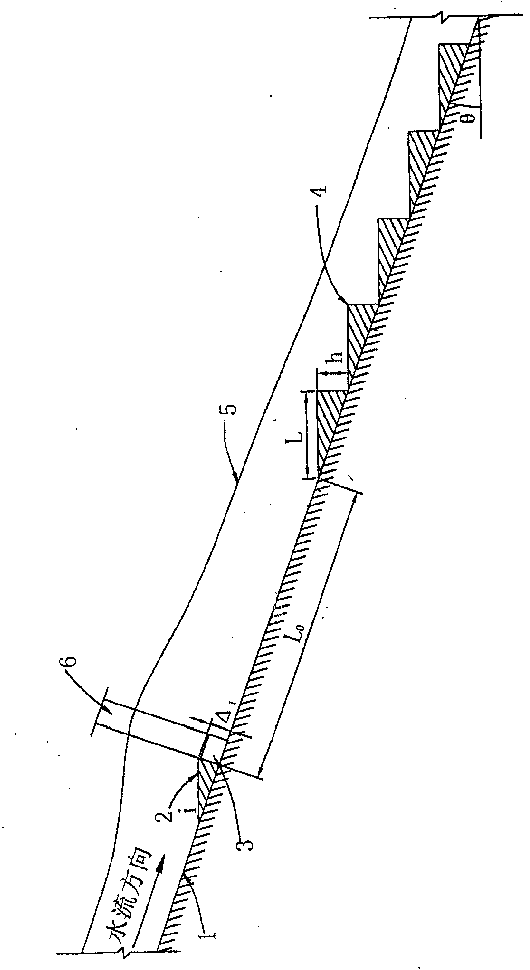
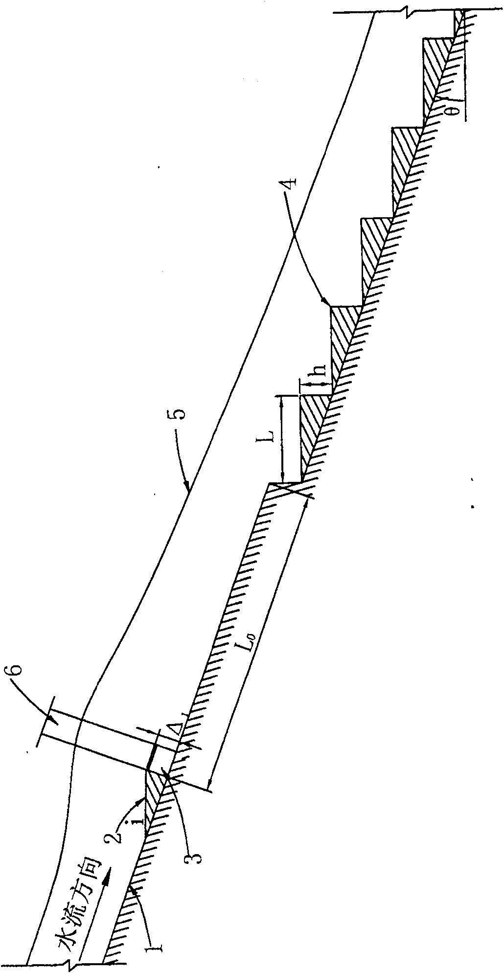
Ladder energy dissipater with doped gas device preposed
An energy dissipating and gas device technology, applied in water conservancy projects, marine engineering, coastline protection, etc., can solve the problems of difficult control of aeration amount and aeration concentration, additional gas supply equipment, etc. The air volume is easy to control and the effect of improving the energy dissipation rate
- Summary
- Abstract
- Description
- Claims
- Application Information
AI Technical Summary
Problems solved by technology
Method used
Image
Examples
Embodiment 1
[0036] The ladder energy dissipation device of the pre-aeration device in this embodiment is used in the project hub of the power station, and the catchment area of the power station is 5317km 2 , the controlled catchment area of the plant site is 5754km 2 . The maximum working head of the spillway of the power station is 140m, and the maximum discharge flow is 760m 3 / s, the designed spillway width is 10m, the bottom slope gradient θ is 18°, and the maximum single-width flow rate is 76m 3 / s.m.
[0037] The stepped energy dissipator of the pre-aeration device in this embodiment has a structure such as image 3 , Figure 4 As shown, it includes a step 4 arranged on the bottom slope 1 of the spillway and an aeration device located upstream of the step. The aeration device is composed of a ridge 2, a ventilation hole 3 and an aeration shaft 7; the ridge 2 is arranged on the bottom slope 1 of the spillway, and its shape is a "wedge", its slope i is 1:5, and its height Δ ...
Embodiment 2
[0041] The stepped energy dissipator of the pre-aeration device in this embodiment is used for a single-width flow rate of 50-70m 3 / s.m, and the dam surface overflow bottom slope gradient θ is 13° as a hydropower project hub.
[0042] The stepped energy dissipator of the pre-aeration device in this embodiment has a structure such as Figure 7 , Figure 8 As shown, it includes a step 4 arranged on the bottom overflow slope 1 of the dam surface and an aeration device located upstream of the step. The aeration device is composed of a ridge 2, an aeration tank 8, a ventilation hole 3 and an aeration well 7; the ridge 2 is arranged on the overflow bottom slope 1 of the dam surface, and its shape is a "wedge block", and its slope i is 1:10, its height Δ 1 = 0.5m, the distance L between the rear end surface and the front end of the first step in the ladder 0 = 42m; the aeration tank 8 is located on the overflow bottom slope of the dam surface and under the ridge 2, the depth of ...
Embodiment 3
[0045] The stepped energy dissipator of the pre-aeration device in this embodiment is used for a single-width flow rate of 50-70m 3 / s.m, and the spillway bottom slope gradient θ is 15° as a hydropower project hub.
[0046] The stepped energy dissipator of the pre-aeration device in this embodiment has a structure such as Figure 11 , Figure 12 As shown, it includes a step 4 arranged on the bottom slope 1 of the spillway and an aeration device located upstream of the step. The aeration device is composed of a lifting ridge 2, a falling ridge 9, a ventilation hole 3 and an aeration well 7; the lifting ridge 2 is arranged on the bottom slope 1 of the spillway, and its shape is a "wedge block", and its slope i is 1:10. its height Δ 1 = 0.5m, the distance L between the rear end surface and the front end of the first step in the ladder 0 = 39.78m; drop sill 9 is located on the bottom slope of the spillway and below sill 2, drop sill height Δ 2 = 1.5m; there are two ventilatio...
PUM
 Abstract
Description
Claims
Application Information
 - R&D
- Intellectual Property
- Life Sciences
- Materials
- Tech Scout
- Unparalleled Data Quality
- Higher Quality Content
- 60% Fewer Hallucinations
Browse by: Latest US Patents, China's latest patents, Technical Efficacy Thesaurus, Application Domain, Technology Topic, Popular Technical Reports.
© 2025 PatSnap. All rights reserved.Legal|Privacy policy|Modern Slavery Act Transparency Statement|Sitemap|About US| Contact US: help@patsnap.com


