
Multiple optical coupling differential precision positioning mechanism for paper banknote identifying movement position and its positioning method

A technology of precise positioning and moving position, which is applied in the processing of coins or valuable banknotes, and the use of optical devices to transmit sensing components, instruments, etc., which can solve the problems of uneven speed, separation of estimated value and actual value, etc., and achieve high positioning accuracy, The effect of overcoming measurement error and simple structure

Inactive Publication Date: 2009-10-28
李庆宁
View PDF4 Cites 0 Cited by
  • Summary
  • Abstract
  • Description
  • Claims
  • Application Information

AI Technical Summary

Problems solved by technology

[0002] At present, in banknote counting machines and banknote sorting machines, the inherent clock signal in the applied equipment circuit is used as the estimated value of the moving distance of the visual object, so that the measurement when the visual object moves in the channel is an open The estimated value of the ring is not exactly the same as the actual movement of the measured object, such as pauses and uneven speeds, resulting in the deviation between the estimated value and the actual value

Method used


Image

  • Multiple optical coupling differential precision positioning mechanism for paper banknote identifying movement position and its positioning method
  • Multiple optical coupling differential precision positioning mechanism for paper banknote identifying movement position and its positioning method
  • Multiple optical coupling differential precision positioning mechanism for paper banknote identifying movement position and its positioning method

Examples


Embodiment Construction

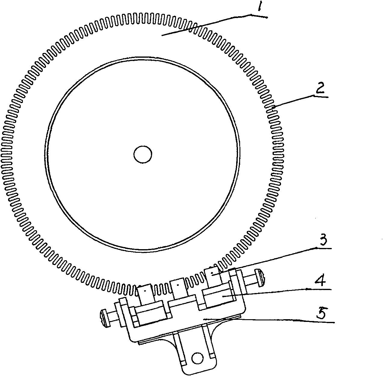
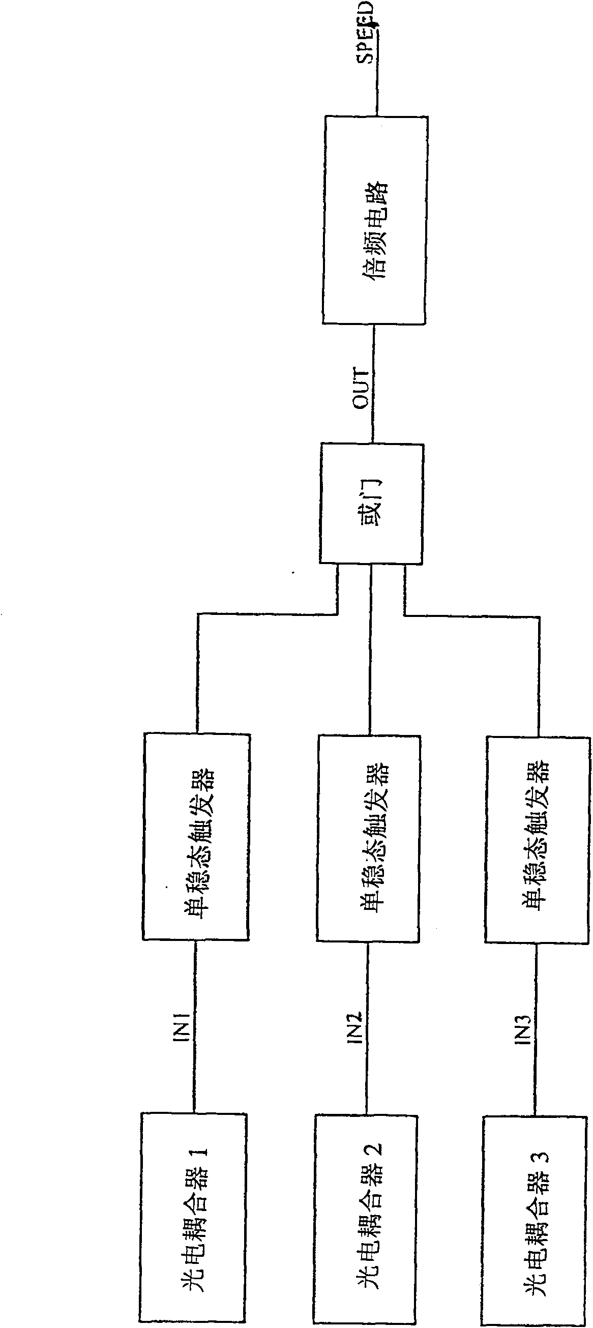
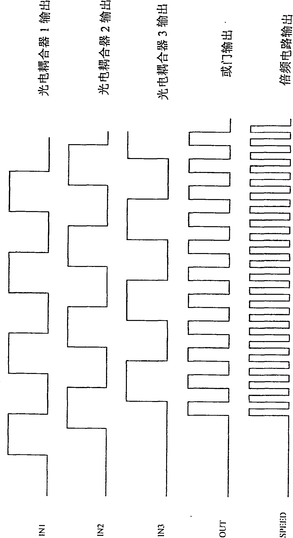
[0012] Refer to attached Figure 1~3 , Banknote identification movement position multi-optocoupler differential precise positioning mechanism and positioning method The mechanism includes a speed measuring disc 1, several photocouplers 3, and a pulse circuit 4. The speed measuring disc 1 is installed on one side of the transmission shaft of the counting machine, and several photocouplers 3 are installed on the edge of the speed measuring disc 1, and the installation distance between the optocouplers 3 constitutes a differential position relationship. The output end of the photocoupler 3 is connected with the input end of the pulse circuit 4 . The photocoupler 3 is installed on the photocoupler circuit mounting bracket 5 . The pulse circuit 4 includes a monostable trigger, an OR circuit, and a multiplier circuit. There are several monostable triggers, the signal input terminals of which are respectively connected to the output terminals of the optocoupler, the output terminal...


PUM


Abstract

A multi-light couple differential precise positioning device of movement position in paper money identification is prepared for erecting speed measurement disc at side of driving shaft on counter, arranging a numbers of photoelectric couplers at edge of speed measurement disc, forming differential position relation on erection space between photoelectric couplers, connecting output end of photoelectric couple to input end of pulse circuit and forming said pulse circuit by single steady-state trigger and OR-gate circuit as well as multi-double frequency circuit.

Description

technical field [0001] The present invention relates to a banknote identification movement position multi-optocoupler differential precise positioning mechanism and a positioning method thereof, which relate to a banknote and bill identification movement position positioning mechanism that is matched with banknote counting machines, sorting machines, paper bill counting machines, and the like. its positioning method. Background technique [0002] At present, in banknote counting machines and banknote sorting machines, the inherent clock signal in the applied equipment circuit is used as the estimated value of the moving distance of the visual object, so that the measurement when the visual object moves in the channel is an open The estimated value of the ring is not exactly the same as the actual movement of the measured object, such as pause and uneven speed, resulting in the deviation between the estimated value and the actual value. Contents of the invention [0003] T...

Claims


Application Information

Patent Timeline
Patent Type & Authority Patents(China)
IPC IPC(8): G05D3/20G01D5/34G07D13/00
Inventor 李庆宁
Owner 李庆宁
Learn More