Gas drying device

A gas drying and gas technology, applied in the field of drying compressed gas devices and drying gas devices, can solve problems such as low efficiency

Active Publication Date: 2009-11-04
ATLAS COPCO AIRPOWER NV
View PDF5 Cites 0 Cited by
  • Summary
  • Abstract
  • Description
  • Claims
  • Application Information

AI Technical Summary

Problems solved by technology

[0005] In addition to desiccant dryers, cooling dryers are also known, but cooling drying in tropical environments is either inefficient or leads to undesirably high energy consumption

Method used


Image

  • Gas drying device
  • Gas drying device
  • Gas drying device

Examples


Embodiment Construction

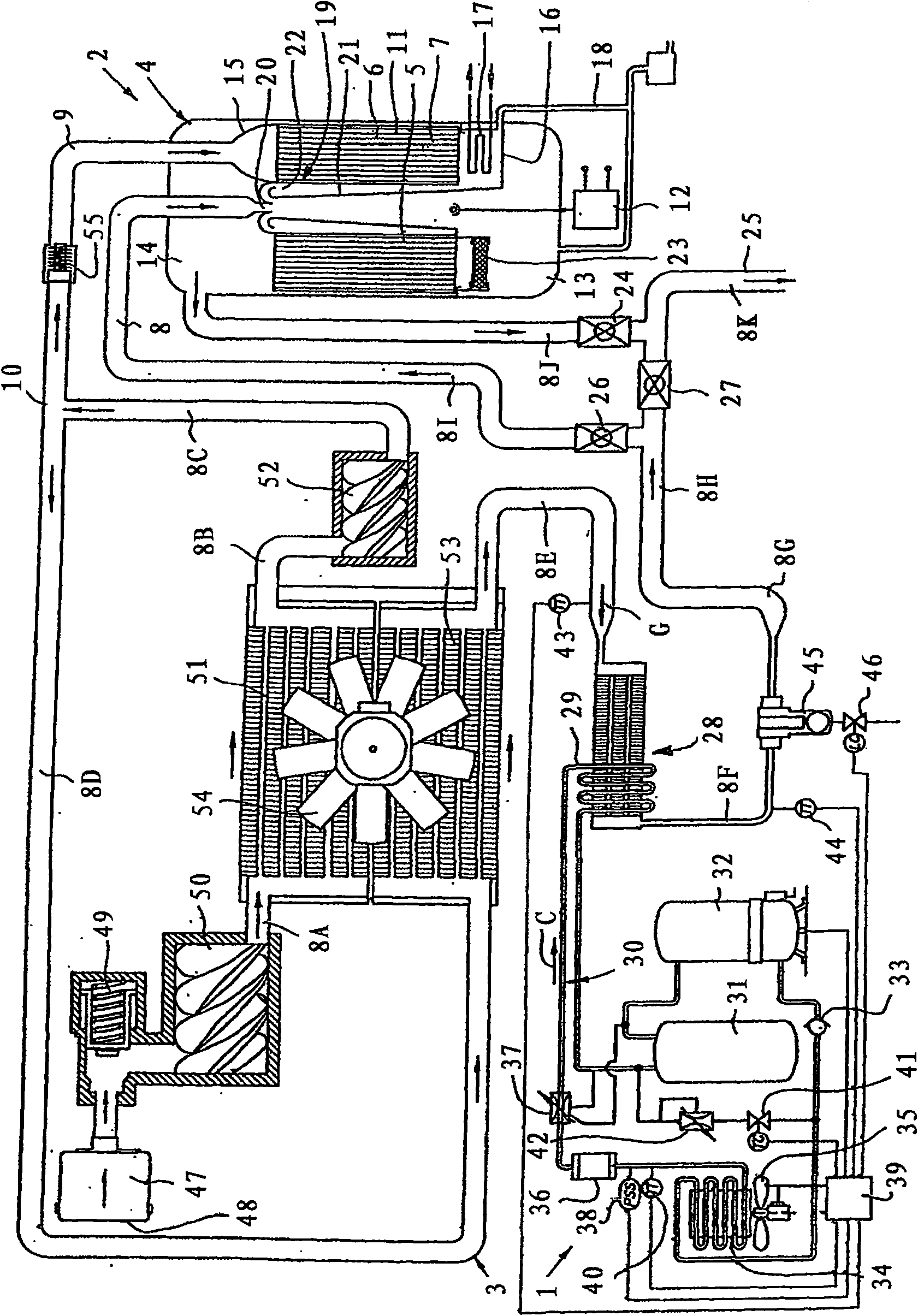
[0012] Such as figure 1 As shown, the gas drying device essentially comprises a cooling dryer 1 , a desiccant dryer 2 and in this embodiment also a compressor part 3 .

[0013] The desiccant dryer 2 is of the type utilizing a pressure tank 4 having a drying zone 5 and a regeneration zone 6 containing an adsorption and / or absorption medium 7 which is led alternately through the drying zone 5 and regeneration zone 6 .

[0014] Furthermore, the device comprises a primary circuit 8 comprising pipes with sections 8A, 8B, 8C, 8D, 8E, 8F, 8G, 8H, 8I, 8J and 8K, the aforementioned cooling dryer 1, the desiccant dryer 2 and the aforementioned The compressor part 3 is integrated into this primary circuit 8 , which makes it possible to first compress the gas to be dried, then at least partially dry it in the cooling dryer 1 and then lead it through the desiccant dryer 2 The drying zone 5 is further dried.

[0015] The device also comprises a secondary circuit 9 which, as a branch 10 in...


PUM


Abstract

A gas drying device comprising: a desiccant dryer (2) utilizing a pressure tank (4) having a drying zone (5) and a regeneration zone (6), the pressure tank (4 ) has an adsorption and / or absorption medium (7) which is alternately guided through a drying zone (5) and a regeneration zone (6); a primary circuit (8), comprising the above-mentioned desiccant dryer (2), the primary circuit ( 8) Make it possible to lead the gas to be dried through the drying zone (5) of the dehumidifying dryer (2); a secondary circuit (9) which makes it possible to lead a part of the gas to be dried through the dehumidification Dryer (2) in the regeneration zone (6) and absorbs moisture there, characterized in that the device also includes a cooling dryer connected upstream of the desiccant dryer (2) in the primary circuit (8) (1).

Description

technical field [0001] The invention relates to a device for drying gas, in particular compressed gas. [0002] In particular, the invention relates to a device for drying gases comprising a so-called desiccant dryer utilizing a pressure tank with a drying zone and a regeneration zone, the tank is equipped with adsorption and / or absorption The medium is guided alternately through the drying zone and the regeneration zone. Background technique [0003] A known problem with such installations is that the gas is not always sufficiently dried for all the required uses, eg under extreme environmental conditions that occur in the tropics. [0004] In high temperature and high humidity conditions, the regenerative capacity of this desiccant dryer is indeed exceeded. [0005] In addition to desiccant dryers, cooling dryers are also known, but cooling drying in tropical environments is either inefficient or leads to undesirably high energy consumption. Contents of the invention ...

Claims


Application Information

Patent Timeline
Patent Type & Authority Patents(China)
IPC IPC(8): B01D53/26
CPCB01D53/261B01D53/26B01D53/265
Inventor B·E·A·万德斯特拉滕B·P·K·范霍维
Owner ATLAS COPCO AIRPOWER NV
Why Eureka
Try Eureka