
Drive device for lock pin

A driving device and lock cylinder technology, used in construction locks, non-mechanical transmission-operated locks, construction, etc., can solve the problems of inability to integrate, difficult, complex electromechanical structure, etc., to improve reliability, service life, driving stroke, etc. Small, wide-ranging effects

Inactive Publication Date: 2009-11-18
HUNAN HONGDA TECH
View PDF5 Cites 0 Cited by
  • Summary
  • Abstract
  • Description
  • Claims
  • Application Information

AI Technical Summary

Problems solved by technology

[0003] The electronic locks currently on the market, whether they work with AC or DC, generally have a working power consumption of several watts (W) to tens of watts (that is, the working voltage is mostly 12-24V, and the working current is 0.2-2A). Due to low efficiency and high power consumption, this type of electronic lock requires a large capacity of the power supply system, so it cannot match the microelectronic control circuit with continuously reduced volume, weight, and power consumption, which also leads to very strict or frequent power consumption requirements in some applications. It is almost impossible to apply in the occasion of power failure, which restricts the popularization and replacement of electronic control locks. Therefore, the application of electronic locks has been limited to high-end commercial places such as hotels and office buildings, and cannot be widely used in homes; Driven by a motor, it is driven by gears and racks. The electromechanical structure is relatively complex, and installation and maintenance require certain professional skills, which is difficult; the entire mechanism consumes high power, and when a fault occurs, the motor self-locking will block the entire mechanism , so this type of electronic lock must be equipped with an ordinary mechanical unlocking mechanism
For the existing ordinary mechanical lock, if it is to be converted into an electronic lock, the entire lock can only be replaced in the prior art, so it cannot be well integrated with the traditional mechanical lock, the replacement cost is high, and it is not conducive to popularization and application.

Method used

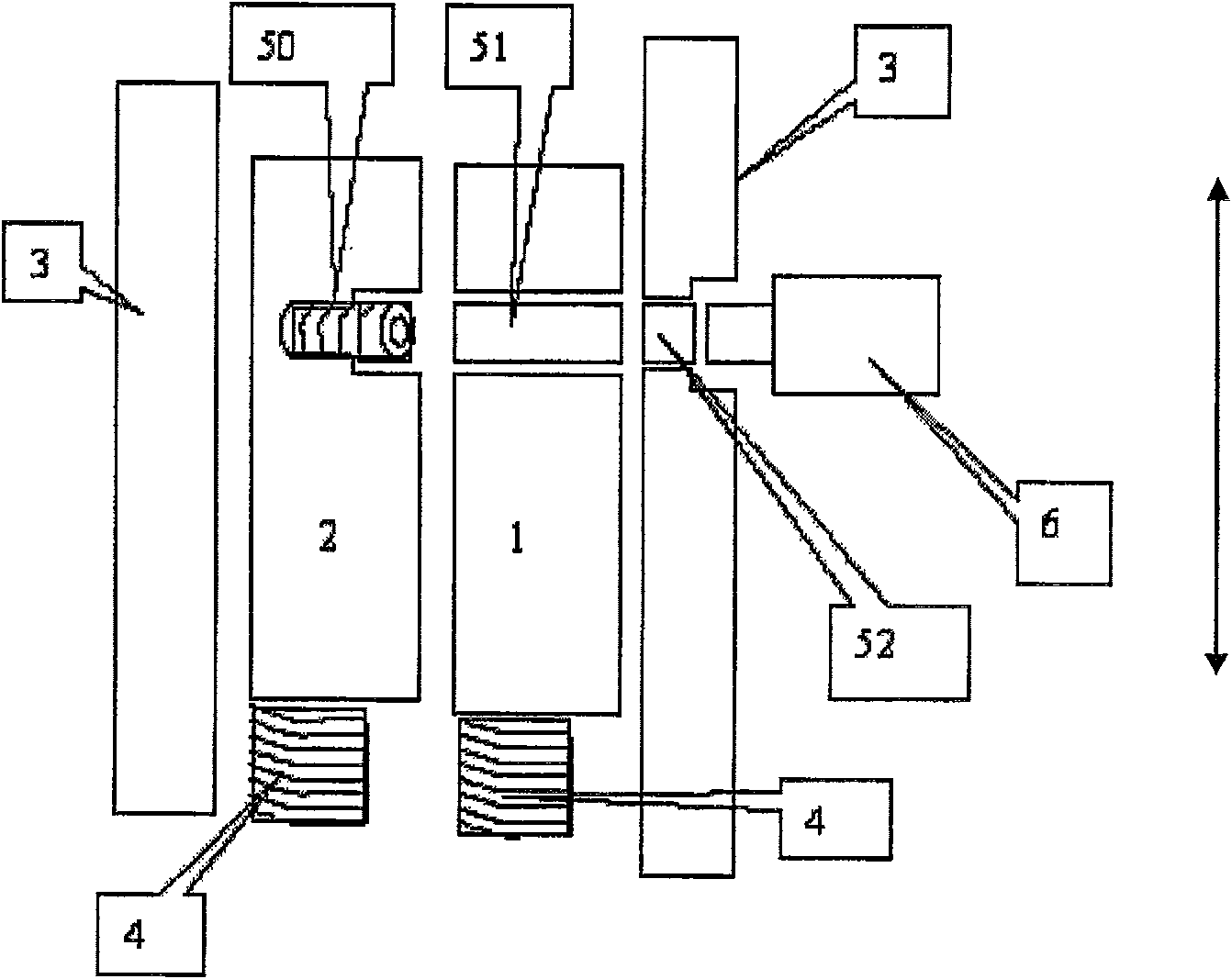
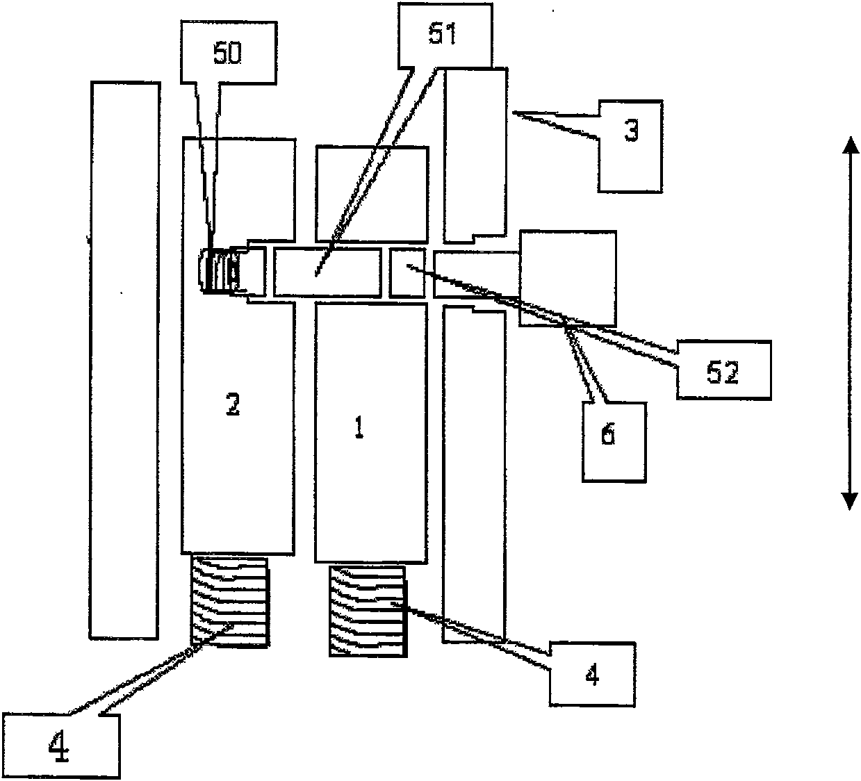
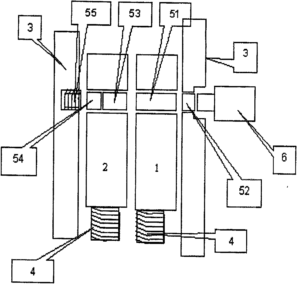

Image

  • Drive device for lock pin
  • Drive device for lock pin
  • Drive device for lock pin

Examples


Embodiment 1

[0050] Embodiment one: if Figure 17 As shown, it is a structural diagram of a pair of back-up driving devices. The bracket 62 is in the shape of a "day" and is fixedly connected to the drive output shaft 61. In each frame of the bracket, there is an ornament 63 that abuts against the inner wall of the frame. The ornament and The output shaft of the micro-motor is connected, and the shape of the pendulum is not limited, as long as the bracket can be pressed under the drive of the micro-motor, so that the drive output shaft 61 can move axially under the guidance of the through hole or other components.

Embodiment 2

[0051] Embodiment two: if Figure 18 shown in Figure 17 The second drive output shaft 64 is set on the opposite direction of the drive output shaft, which is opposite to the direction of motion of the drive output shaft 61. In applications, one drive command produces two opposite drive output actions. This mechanism can applied as Figure 23 In the system shown, special control requirements are met, such as a command is generated simultaneously: one locking action, one separation action; or two locking actions; or two separation actions.

Embodiment 3

[0052] Embodiment three: as Figure 19 As shown, it is a driving device using another shape of the pendant, the principle is the same as Figure 17 The drives shown are identical.


PUM


Abstract

The invention discloses a lock cylinder driving device, which comprises a micro-motor, a pendant, a bracket, and a drive output shaft. The swing of the ornament drives the bracket and drives the output shaft to move. The present invention has simple structure, convenient backup, and it is easy to form multiple sets of independent backup components without increasing the volume; the failure rate of locks using this mechanism is greatly reduced, and the reliability is greatly improved, so that the lock core of the present invention can be directly integrated into car doors and households. Anti-theft doors, safes, etc., are directly compatible with various electronic control systems, and the application is simple and has a wide range of applications.

Description

【Technical field】: [0001] The invention relates to a lock cylinder driving device. 【Background technique】: [0002] Electronic lock is a new type of lock that is more and more widely used, and it is an updated product of traditional mechanical lock. [0003] The electronic locks currently on the market, whether they work with AC or DC, generally have a working power consumption of several watts (W) to tens of watts (that is, the working voltage is mostly 12-24V, and the working current is 0.2-2A). Due to low efficiency and high power consumption, this type of electronic lock requires a large capacity of the power supply system, so it cannot match the microelectronic control circuit with continuously reduced volume, weight, and power consumption, which also leads to very strict or frequent power consumption requirements in some applications. It is almost impossible to apply in the occasion of power failure, which restricts the popularization and replacement of electronic con...

Claims


Application Information

Patent Timeline
Patent Type & Authority Patents(China)
IPC IPC(8): E05B47/02
Inventor 徐文祥
Owner HUNAN HONGDA TECH
Learn More