Stamping machine with elastic supporting work piece support and method for supporting work piece in the stamping machine

A stamping machine and elastic parts technology, applied in metal processing, perforating tools, manufacturing tools, etc., can solve problems such as scratches

Active Publication Date: 2009-11-25
TRUMPF WERKZEUGMASCHINEN GMBH & CO KG
View PDF8 Cites 0 Cited by
  • Summary
  • Abstract
  • Description
  • Claims
  • Application Information

AI Technical Summary

Problems solved by technology

Even in the device proposed by JP07256367A, it happens that the brushes are pressed and the workpiece bears on the die and thus scratches in the case of heavy workpieces

Method used


Image

  • Stamping machine with elastic supporting work piece support and method for supporting work piece in the stamping machine
  • Stamping machine with elastic supporting work piece support and method for supporting work piece in the stamping machine
  • Stamping machine with elastic supporting work piece support and method for supporting work piece in the stamping machine

Examples


Embodiment Construction

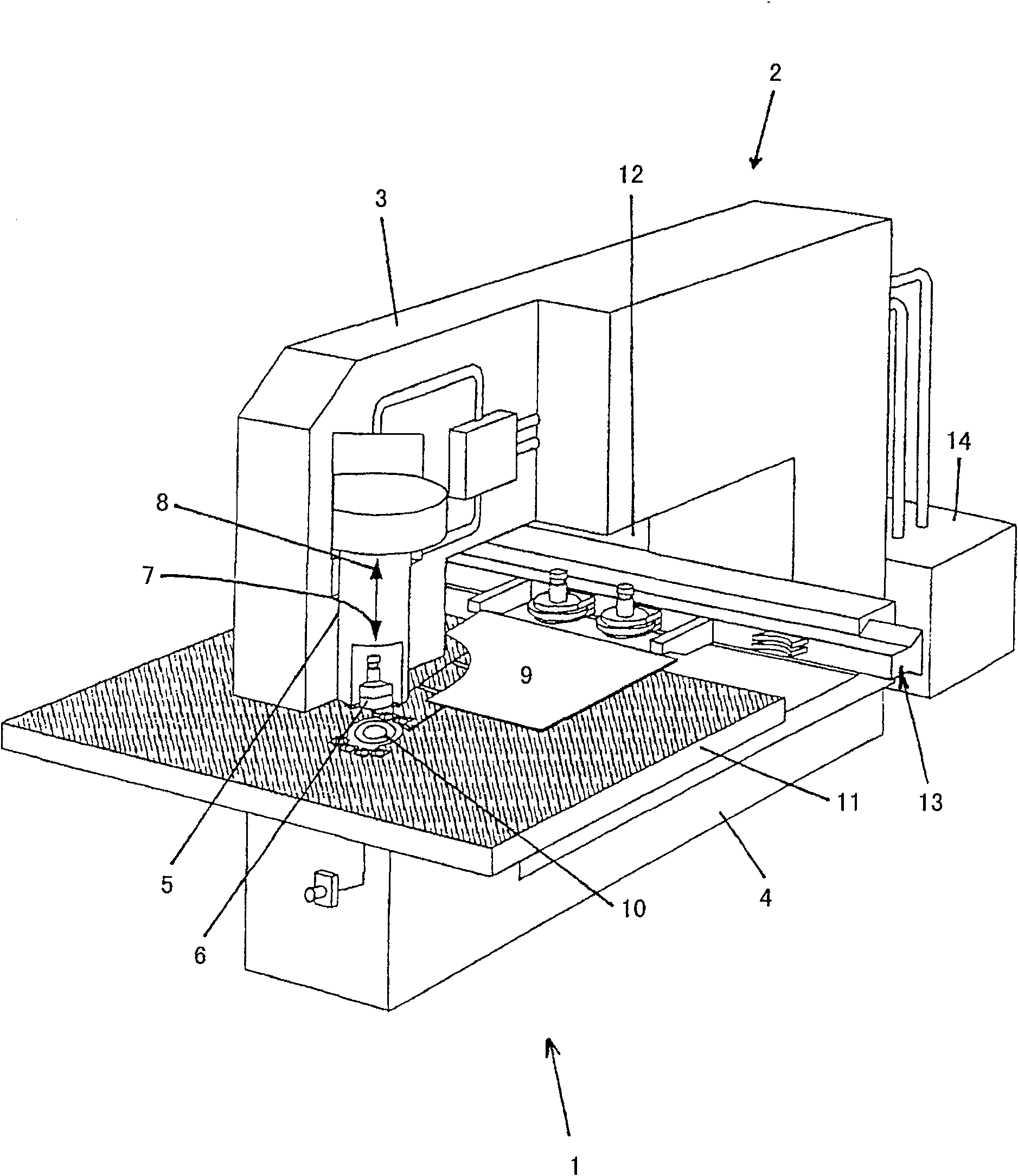
[0027] according to figure 1 , The punching machine 1 has a C-shaped frame 2 with an upper frame part 3 and a lower frame part 4 .

[0028] Mounted on the free end of the upper frame part 3 is a drive 5 for a stamping tool in the form of a punch or for a tool bearing 6 provided with the punch. Via this drive 5 , the tool bearing 6 is linearly movable together with the punch in the machining stroke direction 7 or in the return stroke direction 8 . During the working stroke for machining the workpiece and during the return stroke following the working stroke, a movement is carried out by the tool bearing 6 or the punch in the machining stroke direction 7 or the retraction direction 8 .

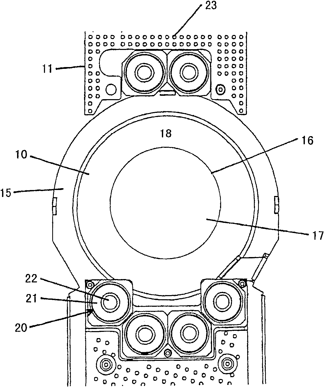
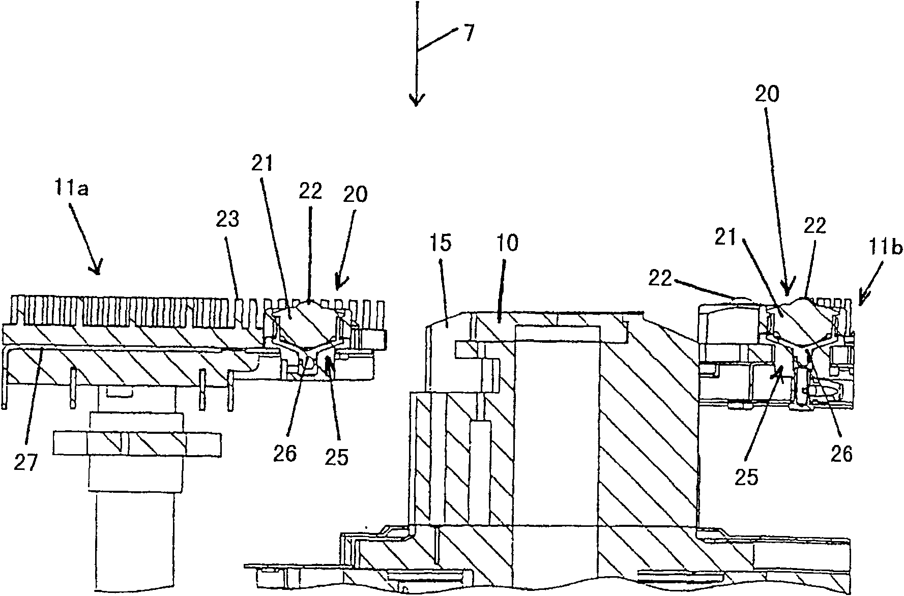
[0029] During the machining of the workpiece, in the illustrated embodiment, during the stamping of the sheet metal 9 , the die interacts with a lower stamping tool in the form of a stamping die 10 . The stamping die is integrated into a workpiece table 11 , which is itself supported on the lo...


PUM


Abstract

A punching machine is provided with a tool holder for a punching tool and a die having a cutting edge which can be passed by the punching tool in a machining stroke direction and a return stroke direction. The machine includes at least one work support, supported by at least one spring element. The work support is arranged in the region of the die, and the spring force of the spring element is adjustable.

Description

technical field [0001] The invention relates to a punching machine with a die receiver for a punching die and a die with a cutting edge by which the punching die can be positioned in the direction of the working stroke as well as in the direction of the return stroke. Motion, wherein at least one workpiece support supported by at least one elastic element is provided in the region of the die, the invention also relates to a method for supporting a workpiece in the region of a die receiver of a stamping press. Background technique [0002] When punching workpieces such as sheet metal, burrs often form on the cutting edge of the die, protruding from the cutting edge in the direction of the return stroke of the die. The form and size of the burr formation depends on different factors such as the material being machined, the cutting geometry or the state of the tool used. After the stamping process, the workpiece is moved perpendicular to the direction of movement of the punch ...

Claims


Application Information

Patent Timeline
Patent Type & Authority Patents(China)
IPC IPC(8): B21D28/34B21D28/26B26D7/20
CPCB21D28/34B26D7/20
Inventor 彼得·比特欧
Owner TRUMPF WERKZEUGMASCHINEN GMBH & CO KG
Why Eureka
Try Eureka