
Injection system

A technology of injection system and injector, which is applied in the direction of charging system, fuel injection pump, low-pressure fuel injection, etc., can solve the problems of large installation space, high manufacturing cost, installation cost and maintenance cost, occupation of injection system, etc., to achieve compact The effect of construction

Inactive Publication Date: 2017-02-22
ROBERT BOSCH GMBH
View PDF5 Cites 0 Cited by
  • Summary
  • Abstract
  • Description
  • Claims
  • Application Information

AI Technical Summary

Problems solved by technology

However, this injection system has the disadvantage that a pressure regulator for regulating the pressure of the fuel to be injected is a necessary part of the injection system
This has the result that the injection system takes up a large installation space, which cannot always be available and can lead to high production, installation and maintenance costs

Method used


Image

  • Injection system

Examples


Embodiment Construction

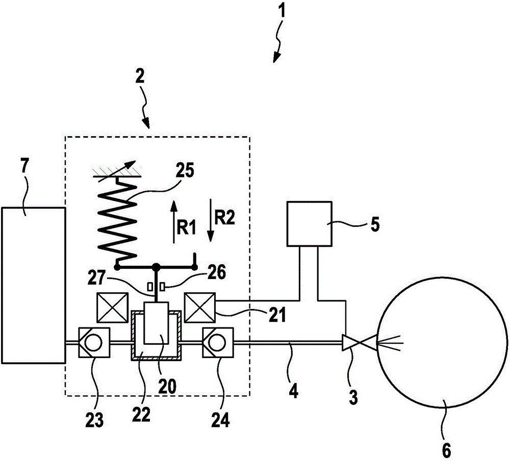
[0018] as from figure 1 As seen in , the injection system 1 according to the invention comprises a fuel pump 2, an injector 3 and a pressure line 4 which is arranged between the fuel pump 2 and the injector 3 and which connects the fuel pump 2 to the Injector 3 is connected. In this case, the pressure line 4 is designed as an elastic hose.

[0019] The fuel pump 2 has a piston 20 , an actuator 21 for actuating the piston 20 , a delivery chamber 22 into which the piston 20 can protrude, an inlet valve 23 , an outlet valve 24 and an operating spring 25 . The working spring 25 is an adjustable coil spring, ie the spring force of the working spring 25 can be adjusted. In addition, the inlet valve 23 and the outlet valve 24 are configured as ball valves. The actuator 21 includes an electromagnetic coil. Other types of actuators, such as piezoelectric actuators or magnetostrictive actuators, are likewise conceivable.

[0020] Furthermore, in this exemplary embodiment the piston...


PUM


Abstract

The present invention relates to an injection system, which comprises a fuel pump (2) having a piston (20), an actuator for actuating the piston (20), a delivery chamber (22) in which the piston (20) is arranged, an inlet valve (23), an outlet valve (24) and a working spring (25) which moves the piston (20) after deactivating the actuator (21) in order to build up pressure in the delivery chamber (22), an injector (3), and a pressure line (4) which is arranged between the fuel pump (2) and the injector (3) and which connects the fuel pump (2) to the injector (3), wherein a delivery pressure of the fuel pump is determined by a spring force of the working spring (25). The present invention further relates to a vehicle, in particular a motorcycle, comprising a fuel pump according to the invention.

Description

technical field [0001] The invention relates to an injection system for a vehicle, especially for a motorcycle or other small internal combustion engines. Another aspect of the invention relates to a vehicle, in particular a motorcycle, comprising such a fuel pump. Background technique [0002] Typically, known injection systems of this type include rotary pumps, pressure regulators and injectors. However, this injection system has the disadvantage that a pressure regulator for regulating the pressure of the fuel to be injected is a necessary part of the injection system. This has the effect that the injection system takes up a large installation space, which cannot always be available and can lead to high manufacturing, installation and maintenance costs. In addition, an electromagnetic piston pump is disclosed in document GB 2478876A, for example. This is an electromagnetic piston pump having a delivery chamber, a piston arranged in the delivery chamber, an actuator in ...

Claims


Application Information

Patent Timeline
IPC IPC(8): F02M37/08F02M69/02F04B17/04F02M55/02F02M59/44
CPCF02M69/02F02M37/08F02M55/02F02M59/442F02M2200/26F04B17/044F04B53/1047
Inventor S·芙洛F·尼切T·阿尔盖尔W·莫伊雷尔
Owner ROBERT BOSCH GMBH
Learn More