
Assembled wheel guiding system arm

A technology of boom and wheel suspension, which is applied to the cantilever mounted on the pivot, suspension, transportation and packaging, etc., can solve the problems of increasing cost pressure and construction period pressure, troublesome molds, and prone to failure, etc., and achieve cost cheap effect

Inactive Publication Date: 2009-12-02
ZF FRIEDRICHSHAFEN AG
View PDF8 Cites 0 Cited by
  • Summary
  • Abstract
  • Description
  • Claims
  • Application Information

AI Technical Summary

Problems solved by technology

[0005] But this has led to the fact that the manufacturer or supplier of the boom of the wheel-guided system is forced to often redesign, construct and produce or provide a variety of different wheel-guided booms
However, in the state of the art of generally one-piece wheel-guided jibs, this has the particular problem that different molds are required for each individual configuration of the wheel-guided jib in order to produce the corresponding The wheel guide system of the jib
Since the arm of the wheel guidance system is a relatively large-surface, but here also complexly shaped and particularly highly loaded component made of high-quality and high-strength material, it is used for the production of the arm of the one-piece wheel guidance system. Most molds are correspondingly labor-intensive and complex and are therefore not only expensive but also prone to failure
[0006] However, increasing cost pressures and time pressures in the structural design, production and supply of motor vehicle components and systems force people to find cost-effective and flexible solutions for the arm brackets for wheel guidance systems. Requirements At the same time, of course, the required high quality of the arm of the wheel-guided system must be maintained or even increased.

Method used


Image

  • Assembled wheel guiding system arm
  • Assembled wheel guiding system arm
  • Assembled wheel guiding system arm

Examples


Embodiment Construction

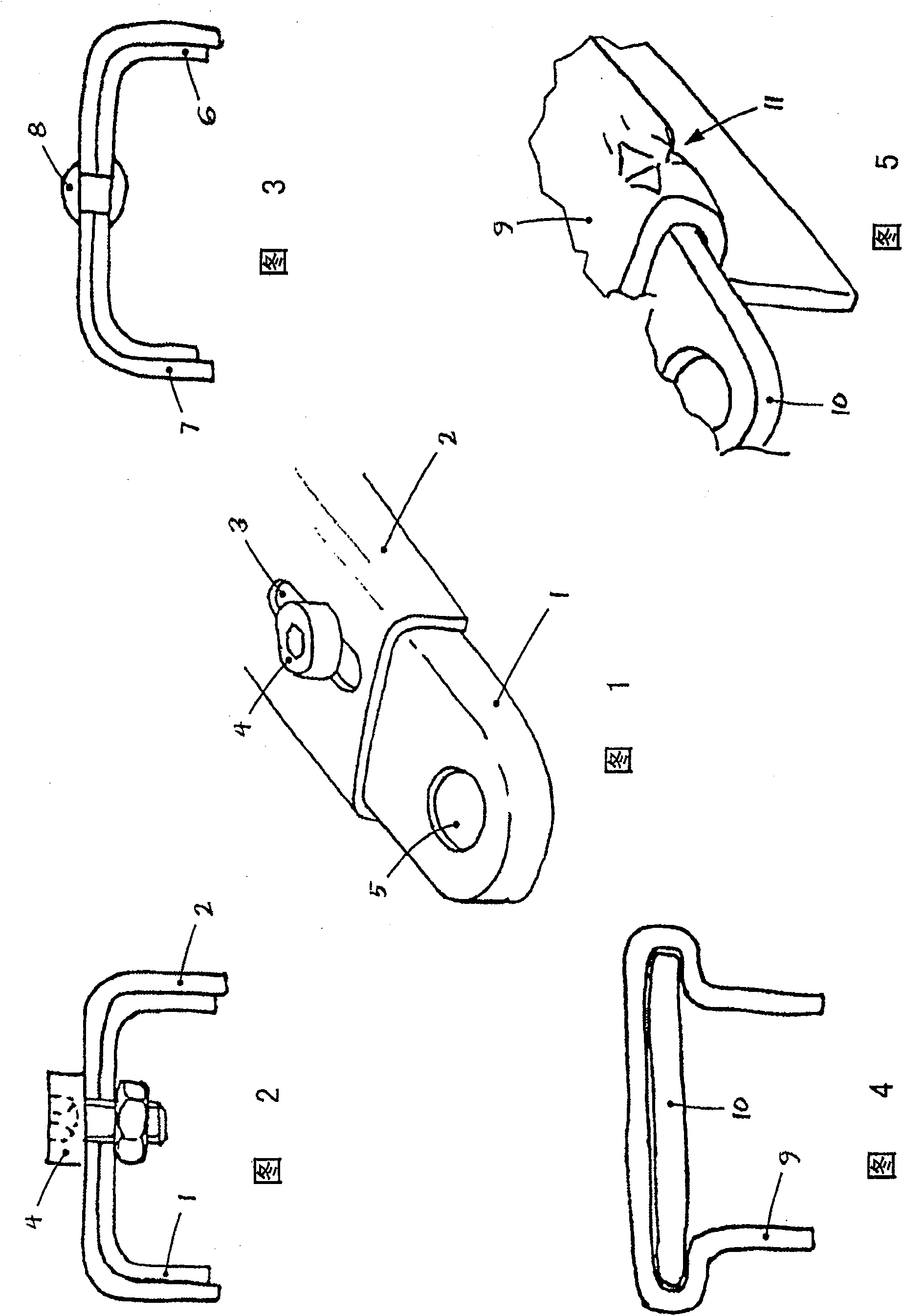
[0035] figure 1 Two profiled parts 1 , 2 or strut arrangements 1 , 2 of a jib having features according to the invention are shown schematically. Wherein, the two profiled parts 1, 2 are connected to each other by means of elongated holes 3 and bolts 4, such as through figure 1 The moldings 1, 2 are described in figure 2 As shown in the cross-sectional diagram in . The profiled parts 1 , 2 thus form part of a jib of a wheel guide system, shown here only in part, for example a strut jib or also a strut structure of a triangular transverse arm.

[0036] It can be seen that the profiled parts 1 , 2 of the arm support according to the invention differ from the prior art in the form of the profiled parts 1 , 2 which can be produced relatively easily by bending or deep drawing. The hole 5 in the profiled part 1 is used to connect the arm, for example by means of a ball joint or an elastomer joint, to a body structure or to a wheel guide structure, such as a steering knuckle, a w...


PUM


Abstract

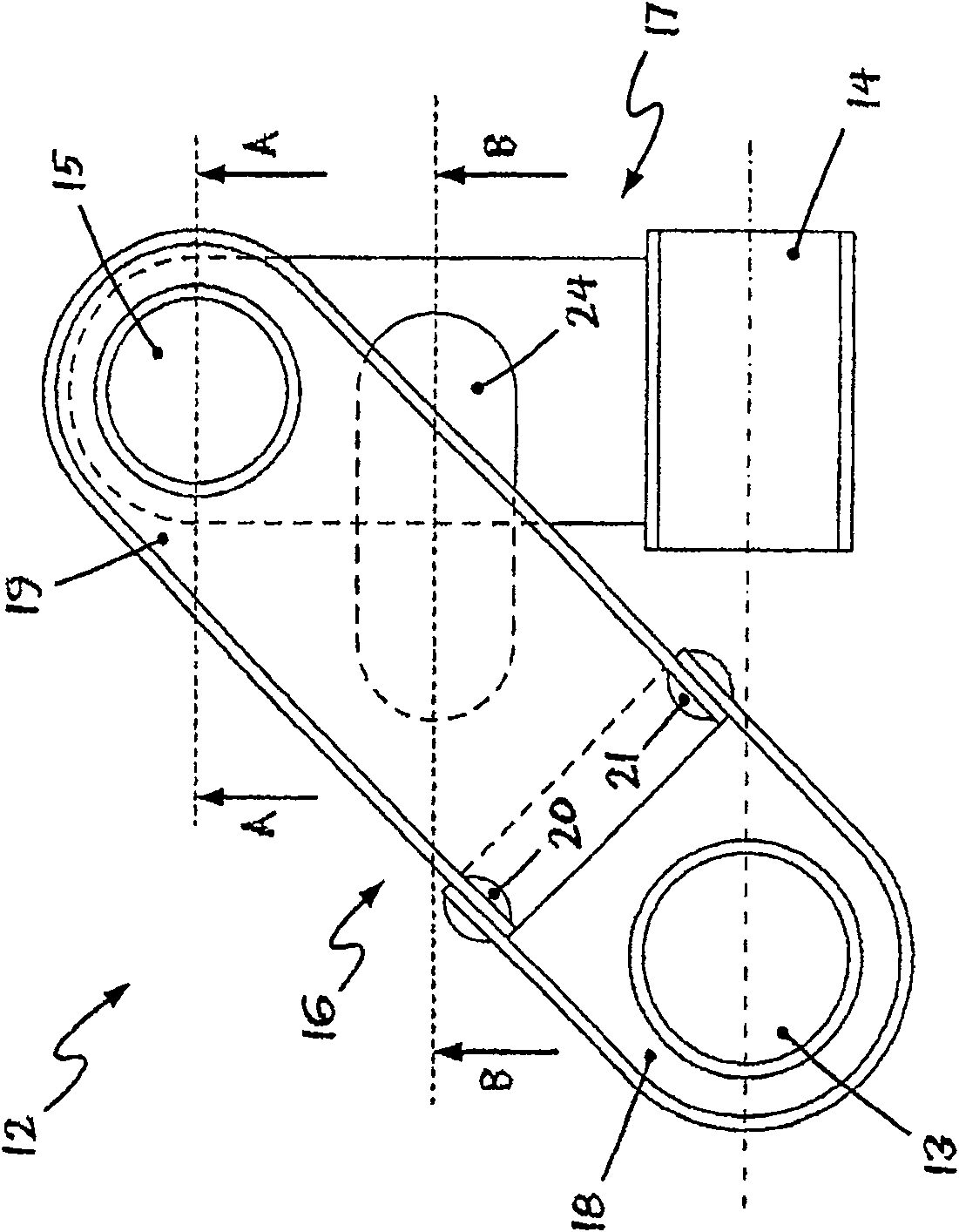
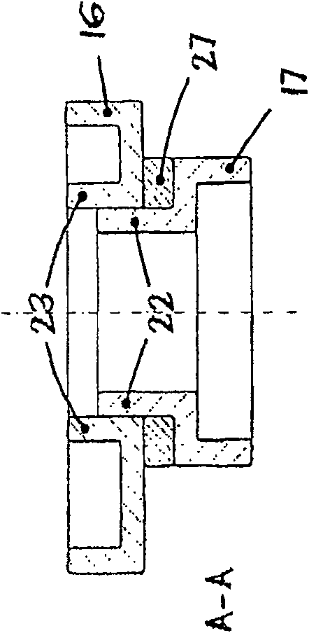
The invention relates to an arm (12), in particular for a wheel suspension of a motor vehicle. The jib (12) comprises at least two attachment points (13, 14, 15) for pivotably connecting the jib (12) to a body structure and a wheel guide structure and a means for making these attachment points Linked strut configurations. The jib of the invention is characterized in that the strut arrangement is assembled from at least two strut devices (17, 18, 19), wherein the strut devices are a single molded part with a substantially planar or open cross-sectional shape . The present invention provides a boom modular system for designing and producing arbitrarily wide-ranging configurations of axle systems and wheel suspensions of motor vehicles. There are comparatively no appreciable tooling costs for producing various variants of the jib or new jib designs. Due to the wide variety of applications and the simple shape of the modular structural parts, these structural parts can be produced in a particularly cost-effective manner in a large and predictable number of workpieces.

Description

technical field [0001] The invention relates to an assembled wheel guide system arm, for example a cross arm, in particular for a wheel suspension of a motor vehicle. Background technique [0002] Arms of the type mentioned at the outset can be used in almost all types of motor vehicles and in wheel suspensions of almost all types of motor vehicles. Arms of this type, such as transverse arms, but also longitudinal arms, three-dimensional arm shafts (Raumlenkerachsen) and similar structures have the task on motor vehicles of connecting the corresponding wheels or the corresponding wheels The wheel carrier is connected to the body structure so that only these structurally defined degrees of freedom remain for the wheel or the wheel carrier. Most of these degrees of freedom mainly manifest themselves in the free movement of the wheel or the wheel carrier in the vertical direction in order to be able to compensate for wheel movements caused by uneven ground. [0003] In most c...

Claims


Application Information

Patent Timeline
Patent Type & Authority Patents(China)
IPC IPC(8): B60G7/00B62D27/06
CPCB60G7/001B60G2206/8206B60G7/00B62D27/00B60G7/02B62D27/06
Inventor J·施米茨F·纳赫巴B·埃勒斯J·塔莫塞特M·韦勒丁K·-H·卡尔瓦斯T·许特纳L·科比尔R·泰杰罗卡斯特罗J·R·伊斯基耶多努涅斯
Owner ZF FRIEDRICHSHAFEN AG
Learn More