
Connector structure with lock mechanism

A locking mechanism and connector technology, which is applied to igniters with fuel, couplings, mechanical equipment, etc., can solve the problems of hindering miniaturization, troublesome and defective removal of supply equipment, etc., and achieve the effect of reliable locking

Inactive Publication Date: 2009-12-02
TOKAI
View PDF7 Cites 0 Cited by
  • Summary
  • Abstract
  • Description
  • Claims
  • Application Information

AI Technical Summary

Problems solved by technology

[0003] However, in the conventional connector structure, the gas igniter as a receiving device for using fluid and the gas cylinder as a supply device for accommodating fluid and replenishing injection to the gas igniter are connected only when the fluid is replenished and injected into the gas igniter. , is not a mechanism that is always connected, so the mechanism is relatively simple
[0004] However, depending on the purpose of use, it is sometimes required that the receiving device is always connected to the supply device containing the fluid to supply the contained fluid. At this time, the mechanism as the connecting part can be simply constituted as having a pump on the receiving device side. The fluid delivery structure in the supply device, but it is necessary to install a fuel pump and its control mechanism on the receiving device side, which will make the receiving device complicated and hinder miniaturization
[0005] As mentioned above, since there is no need to provide a pump on the side of the receiver, it is preferable to supply the fluid using a supply device such as the above-mentioned gas cylinder that contains fluid in a pressurized state. However, when the supply device is not installed in a securely connected state, Then there is a problem of fluid leakage and poor fluid supply
[0006] In addition, in order to prevent the connected feeding device from falling off due to vibration, etc., it is necessary to provide a locking mechanism, and if the feeding device is inserted into the receiving device and installed, there is a problem that it is troublesome to remove the feeding device after use.

Method used


Image

  • Connector structure with lock mechanism
  • Connector structure with lock mechanism
  • Connector structure with lock mechanism

Examples


no. 1 example

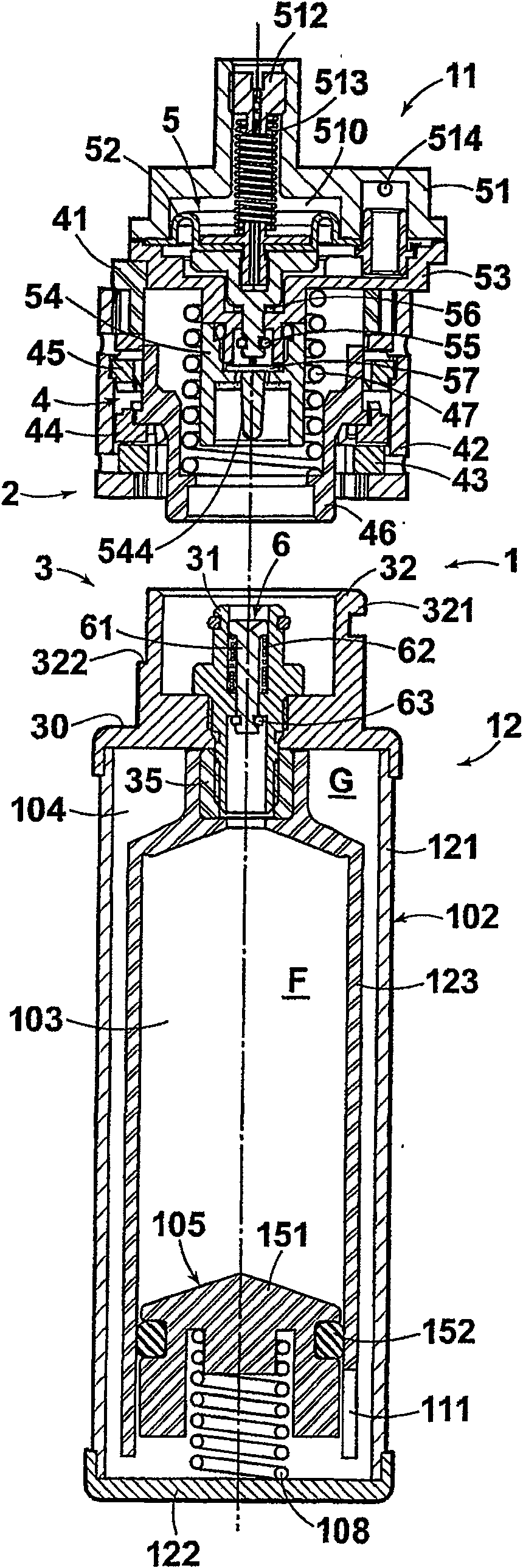
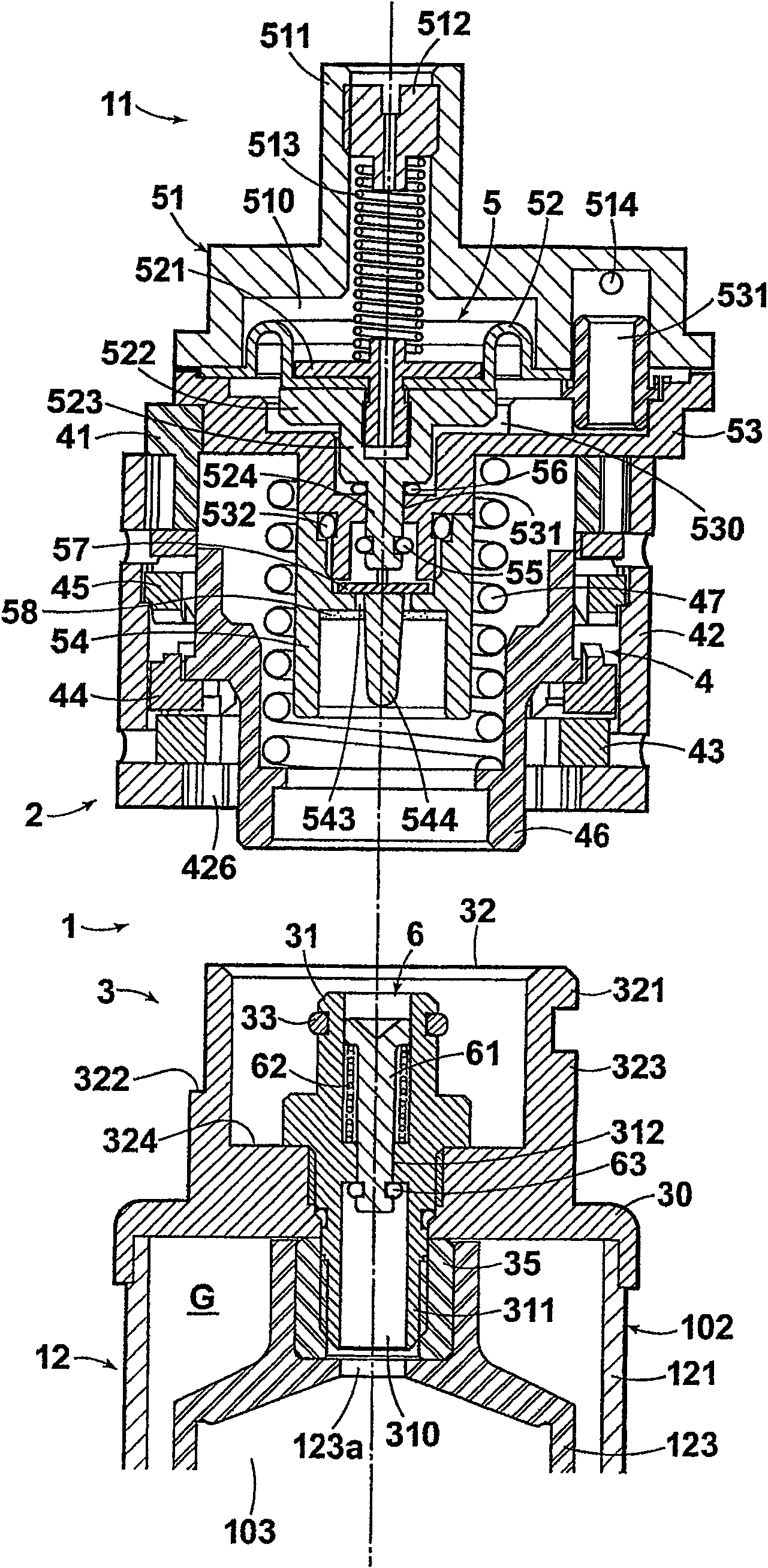
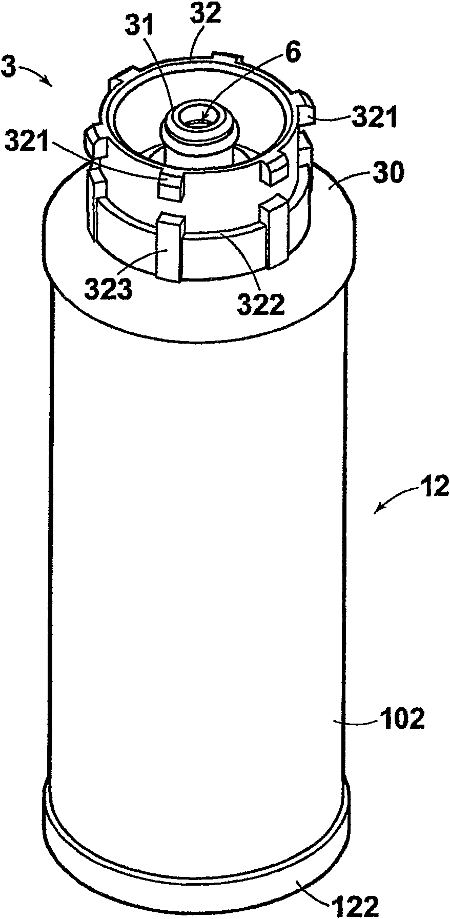
[0041] figure 1 and figure 2 The connector structure 1 of the embodiment is composed of a receiving connection part 2 provided on a receiving device 11 such as a fuel cell that uses fluid such as liquid fuel, and a supply device such as a fuel cartridge that is provided in a pressurized state to supply the fluid. The supply connection part 3 on 12 constitutes, when the fluid F is supplied from the supply device 12 to the receiving device 11, the receiving connection part 2 and the supply connection part 3 are connected to a locked state by the fixing mechanism 4 (pawl mechanism). The receiving connection part 2 has the main part of the fastening mechanism 4, and also has the pressure regulating mechanism 5 (adjusting mechanism) for regulating the supply fluid to a constant secondary pressure. On the other hand, the supply connection part 3 has a valve mechanism 6 having a lever valve 61 biased in the valve-closing direction by a spring 62 in the plug-shaped supply connection...

no. 2 example

[0095] Figure 14 It is an exploded perspective view of the main parts of the fastening mechanism (pawl mechanism) of the second embodiment, Figure 15 Indicated by removing part of the bracket Figure 14 The diagram of the action state of the fastening mechanism.

[0096] The difference between this embodiment and the first embodiment is that: the surface of the first ring 43 that contacts the second ring 44 has unevenness 434 . Others are the same as those in the first embodiment, and are marked with the same symbols, and descriptions are omitted.

[0097] In this embodiment, with the upward movement of the supply connection part 3, when the guide protrusion 442 of the second ring 44 disengages from the second guide groove 424, as Figure 15 As shown, the second ring 44 obtains a rotational force by contacting the slope of the lower surface of the third ring 45, and also obtains a rotational force toward the rotational direction d by contacting the unevenness 434 of the f...

no. 3 example

[0101] Figure 16 It is an exploded perspective view of the main parts of the fixing mechanism (pawl mechanism) of the third embodiment, Figure 17 and Figure 18 Is only represented by the main parts Figure 16 The cross-sectional view of the action state of the fastening mechanism.

[0102] In this embodiment, the second ring 44 is always biased by the release spring 47 to produce a rhythmic click sound of the ratchet.

[0103] Specifically, by arranging spring brackets 48 of different shapes, the biasing force of the release spring 47 does not directly act on the supply connection portion 3, but acts on the separation direction through the second ring 44, and other parts and the second ring 44 are separated. One embodiment is the same and marked with the same symbol, and the description is omitted.

[0104] The spring bracket 48 of this embodiment includes: a cylindrical upper tube portion 481; a lower tube portion 482 having a smaller outer diameter than the upper tube...


PUM


Abstract

In the connector structure composed of the supply connection part for supplying the fluid and the receiving connection part for receiving the supply of the fluid, the connection can be reliably performed in the locked state by simple actions, and the release can be reliably performed by simple actions. take out. The connector structure includes a fixing mechanism (4) and a force applying mechanism (47), and the fixing mechanism (4) has an action part (44) that moves along with the connection action of the supply connection part (3) and the receiving connection part (2). ), with the movement of the action member (44), it is maintained in a locked state that fixes the connection state of the supply connection part (3) and the reception connection part (2), and the next push-in of the supply connection part (3) Operation, the action part (44) moves further, releases the locking state of the supply connection part (3) and the reception connection part (2), and the force application mechanism (47) separates the supply connection part (3) from the reception connection part (2) When force is applied in the direction of the fixing mechanism (4), fluid can be supplied from the supply connection part (3) to the reception connection part (2).

Description

technical field [0001] The present invention relates to a connector structure with a locking mechanism comprising a supply connection part for supplying fluid and a receiving connection part for receiving the supply of the fluid. Background technique [0002] As a conventional receiving device for using fluid and a supply device for supplying the fluid, for example, there is a combination of a fuel injection type igniter and a gas cylinder for fuel injection. The connector structure generally adopts the following structure: the injection port on the side of the igniter Valves are respectively provided at the discharge outlets on the side of the gas storage cylinder and the gas storage cylinder, and the two valves are opened due to the pushing action of the gas storage cylinder, so that the fluid in the gas storage cylinder is injected into the igniter (for example, refer to Japanese Publication No. 39-14343 and Japanese Mihiko Publication No. 3-35972). [0003] However, in ...

Claims


Application Information

Patent Timeline
Patent Type & Authority Patents(China)
IPC IPC(8): F23K5/02F17C13/00F16L37/36F23Q2/16F16L37/24
Inventor 臼井秀人中村保昭
Owner TOKAI
Learn More