Micro-wave oven

A technology for microwave ovens and oven doors, which is applied to oven/stove doors, household ovens/stoves, oven/stove brackets/shelves, etc. It can solve the problems of steaming, occupying a lot of space, and inconvenient users, and achieves a simple and reasonable structure , Low production cost, and the effect of improving the utilization rate

Active Publication Date: 2009-12-09
GUANGDONG GALANZ MICROWAVE OVEN & ELECTRICAL APPLIANCES MFG
View PDF7 Cites 3 Cited by
  • Summary
  • Abstract
  • Description
  • Claims
  • Application Information

AI Technical Summary

Problems solved by technology

[0002] At the end of common microwave oven cooking, the temperature in the oven cavity is quite high, and the entire oven cavity is steaming hot. Even in the forced hot air convection mode, the temperature of the cavity still reaches about 250°C. Cooked food, which brings inconvenience to the user, for this situation, some manufacturers have made some improvements, as disclosed in the Chinese Patent Document No. CN200943889Y a kind of conveyor belt microwave oven, it is characterized in that: comprise The first roller and the second roller, the outer circumference of the first roller and the second roller is installed with the conveyor belt, the first guard plate and the second guard plate are installed on the base, the first guard plate and the second guard plate are respectively located on both sides of the conveyor belt, and the base The bracket is installed on the upper bracket, the lifting device is installed on the bracket, the cover is installed on the lifting device, the shell is installed on the second guard plate, the magnetron and the microwave oven power supply are installed in the shell, and the magnetron is connected to the microwave oven power supply through a wire
The conveyor-belt microwave oven with this structure can automatically transfer food out at the end of cooking, which has certain convenience, but it is bulky, takes up a lot of space, and has high production cost, so it is not suitable for home use.

Method used


Image

  • Micro-wave oven
  • Micro-wave oven
  • Micro-wave oven

Examples


Embodiment Construction

[0012] The present invention will be further described below in conjunction with the accompanying drawings and embodiments.

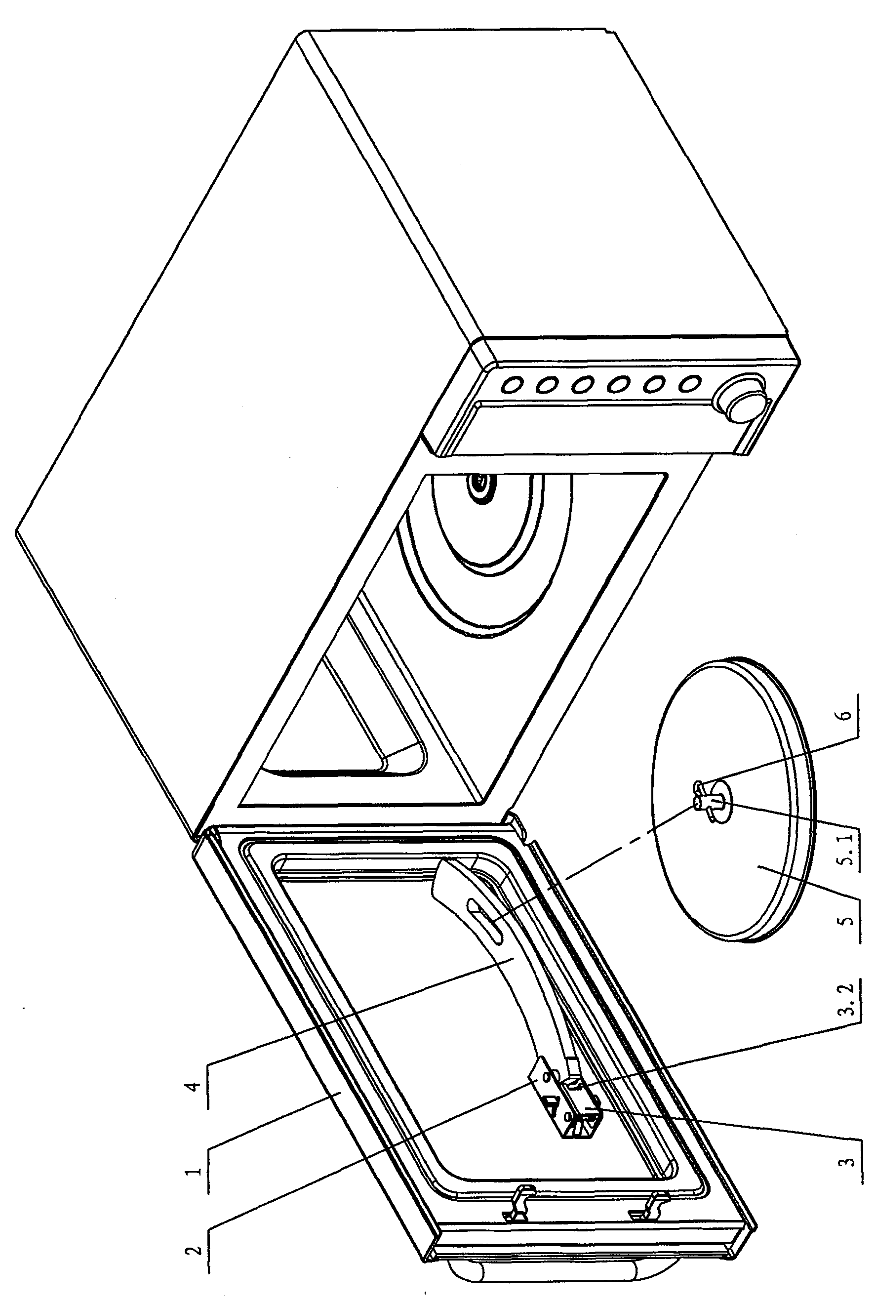
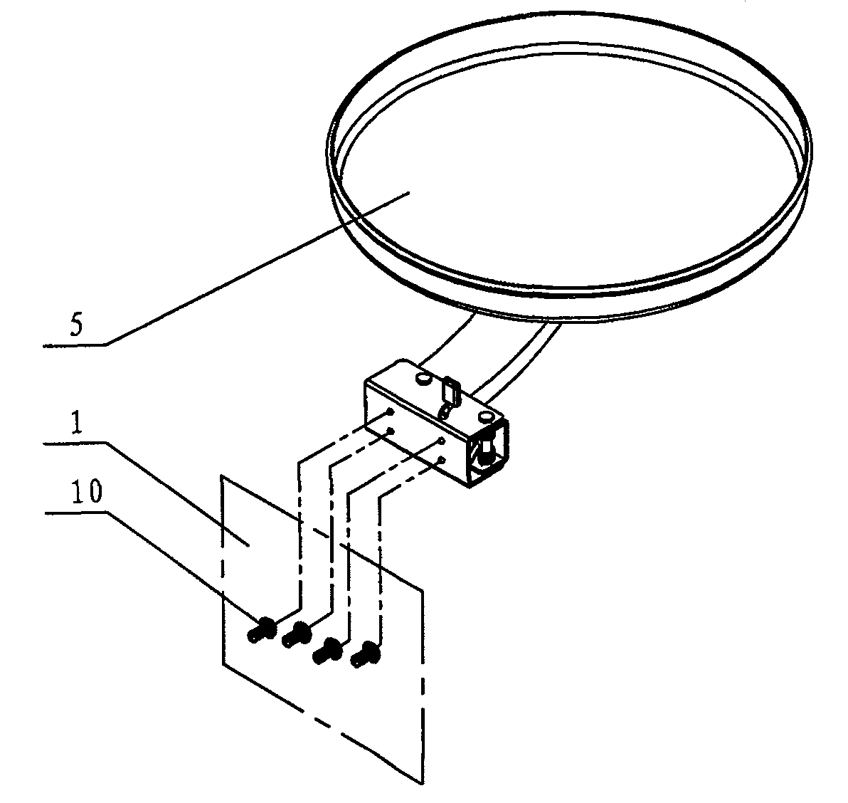
[0013] In the figure: 1 is the furnace door, 2 is the support, 2.1 is the guide groove, 3 is the limit block, 3.1 is the wrench, 3.2 is the limit opening slot, 4 is the rotating arm bracket, 4.1 is the chute, 4.2 is the limit Boss 5 is a food tray, 5.1 is a positioning column, 6 is a latch, 7 is a rotating shaft, 8 is a torsion spring, 9 is a fixed shaft, and 10 is a screw.

[0014] see figure 1 - Fig. 5, the microwave oven includes a furnace door 1, which is provided with a door-opening food take-out mechanism, which includes a food tray 5 connected to the inner side of the furnace door through a rotating arm bracket 4, and the food tray is circular or oval or square.

[0015] A support 2 is provided on the furnace door 1, and a limit block 3 is arranged on the support. One end of the limit block is hinged on the support through a fixed shaft 9. A to...


PUM


Abstract

The invention provides a microwave oven, comprising an oven door, wherein the oven door is provided with an open-door food-out mechanism; the mechanism comprises a food tray connected with the inner side of the oven door by a rolling arm bracket; the oven door is also provided with a supporting base, the rolling arm bracket is hinged with the supporting base by a rotor axle; the food tray is hinged with the rolling arm bracket; the rolling arm bracket is provided with a bar chute, the food tray is provided with a positioning post of which one end passes through the chute and is fixed by a bolt; the supporting base is provided with a limitation block which has one end hinged with the supporting base with a dead axle, a tension spring sleeve which is arranged on the dead axle has one end abutted against the supporting base and the other end abutted against the limitation block, the supporting base is provided with a guiding groove, the other end of the limitation block is provided with a spanner which has one end pass through the guiding groove and a limitation opening groove. The invention has the advantages of simple and reasonable structure, small volume, low manufacturing cost, flexible operation, safety and reliability.

Description

technical field [0001] The invention relates to a microwave oven, in particular to a door-opening food carrying-out mechanism of the microwave oven. Background technique [0002] At the end of common microwave oven cooking, the temperature in the oven cavity is quite high, and the entire oven cavity is steaming hot. Even in the forced hot air convection mode, the cavity temperature still reaches about 250°C. Cooked food, which brings inconvenience to the user, for this situation, some manufacturers have made some improvements, as disclosed in the Chinese Patent Document No. CN200943889Y a kind of conveyor belt microwave oven, it is characterized in that: comprise The first roller and the second roller, the outer circumference of the first roller and the second roller is installed with the conveyor belt, the first guard plate and the second guard plate are installed on the base, the first guard plate and the second guard plate are respectively located on both sides of the con...

Claims


Application Information

Patent Timeline
Patent Type & Authority Patents(China)
IPC IPC(8): F24C7/02F24C15/02F24C15/16
Inventor 陈锦聪
Owner GUANGDONG GALANZ MICROWAVE OVEN & ELECTRICAL APPLIANCES MFG
Why Eureka
Try Eureka