Supercharge Your Innovation With Domain-Expert AI Agents!

Braking equipment for motor vehicles

一种制动设备、机动车辆的技术,应用在制动器、车辆部件、制动传动装置等方向

Inactive Publication Date: 2009-12-16
CONTINENTAL TEVES AG & CO OHG
View PDF5 Cites 0 Cited by
  • Summary
  • Abstract
  • Description
  • Claims
  • Application Information

AI Technical Summary

Problems solved by technology

In the braking system of the prior art, it is considered to be disadvantageous that it is only possible to support driving by the vehicle when the electronics and the energy supply devices (battery and body network) present in the vehicle are active. operator's operating force

Method used


Image

  • Braking equipment for motor vehicles

Examples


Embodiment Construction

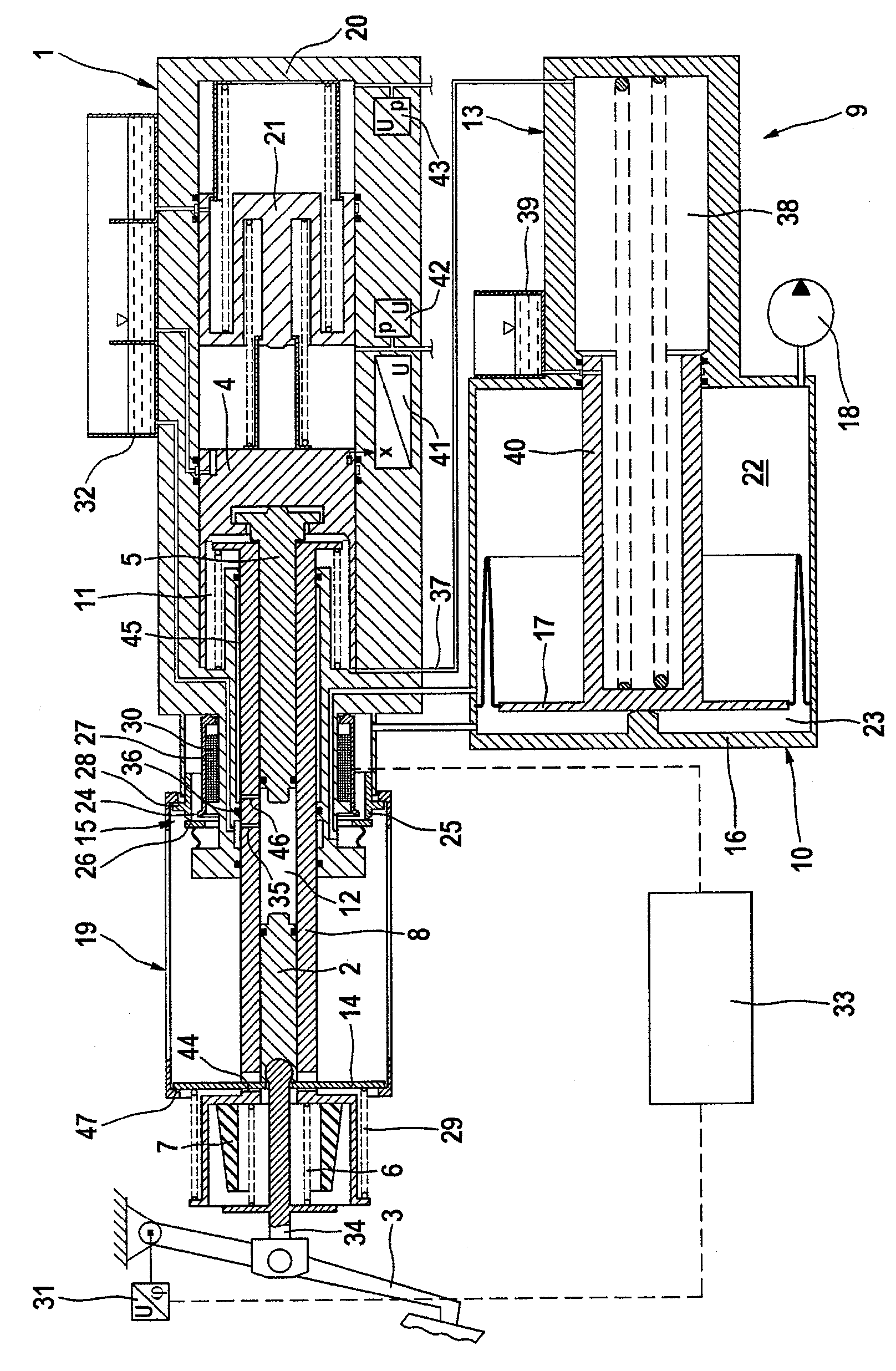
[0034] The brake system according to the invention shown in the figures has a brake pedal 3 which is operatively connected to the first piston 2 via an operating rod 34 . The brake pedal stroke can be detected by a rotational angle sensor 31 . Furthermore, a second piston 4 is provided, which is the actuating piston of master brake cylinder 1 . In the example shown, the master actuating cylinder 1 is designed as a tandem master cylinder, in whose master cylinder housing 20 a further piston 21 is connected to the second piston 4 . The wheel brakes of the vehicle can be connected to master brake cylinder 1 via a controllable wheel brake pressure modulation module, not shown, wherein an electronic control unit and regulating unit, also not shown, is assigned to the wheel brakes. Pressure modulation module. As an alternative or in addition to the angle of rotation sensor shown, a travel sensor can be provided which detects the actuation travel of the push rod 34 or of the first ...


PUM


Abstract

The invention relates to a braking device, comprising: a master cylinder (1) with a master cylinder housing (20) to which a wheel brake cylinder can be connected; a push rod (34) for transmitting an operating force and a brake the first piston (2) coupled with the moving pedal (3); the second piston (4) for operating the master cylinder (1); the third piston (5) hydraulically operable by the first piston (2); at least An elastic element (6, 7) forming a pedal travel simulator which provides a pleasant pedal feel for the driver of the vehicle in the "brake-by-wire" operating mode; for coupling the first piston (2) and means for the movement of the third piston (5); an intermediate space (11) available for hydraulic pressure, the pressurization of which produces hydraulic pressure on the second piston (4) and the third piston (5); And an electrically controllable pressure supply module (9) which can both fill and empty the intermediate space (11) with pressurized fluid. In order to support the operating force even in the event of failure of the electronic control unit or the electrical energy supply, a fourth piston (8) is provided, which can pass through the elastic elements (6, 7) on the input side and the intermediate space ( The hydraulic force in 11) is acted by two forces in opposite directions, and the brake equipment is also provided with a device (14, 19, 15) so that the pressure supply module (9) can be controlled according to The position of the fourth piston (8) obtained by the action of the force is controlled.

Description

technical field [0001] The invention relates to a braking system for a motor vehicle comprising: [0002] a master cylinder with a master cylinder housing to which the wheel brake cylinders can be connected, [0003] a first piston, which is coupled to the brake pedal via a push rod transmitting an operating force, [0004] a second piston for operating the master cylinder, [0005] a third piston hydraulically operable by the first piston, [0006] at least one elastic element forming a pedal travel simulator which provides a pleasant pedal feel for the driver of the vehicle in the "brake-by-wire" operating mode, [0007] means for coupling the movement of the first piston and the third piston, [0008] an intermediate space available for hydraulic pressure, the pressurization of which produces hydraulic pressure on the second and third pistons, and [0009] An electrically controlled pressure supply module may be used which enables both filling and emptying of the inter...

Claims


Application Information

Patent Timeline
Patent Type & Authority Patents(China)
IPC IPC(8): B60T8/40B60T13/14
CPCB60T13/146B60T8/4077B60T8/40B60T13/14
Inventor S·德鲁姆
Owner CONTINENTAL TEVES AG & CO OHG
Features
  • R&D
  • Intellectual Property
  • Life Sciences
  • Materials
  • Tech Scout
  • Unparalleled Data Quality
  • Higher Quality Content
  • 60% Fewer Hallucinations
Learn More